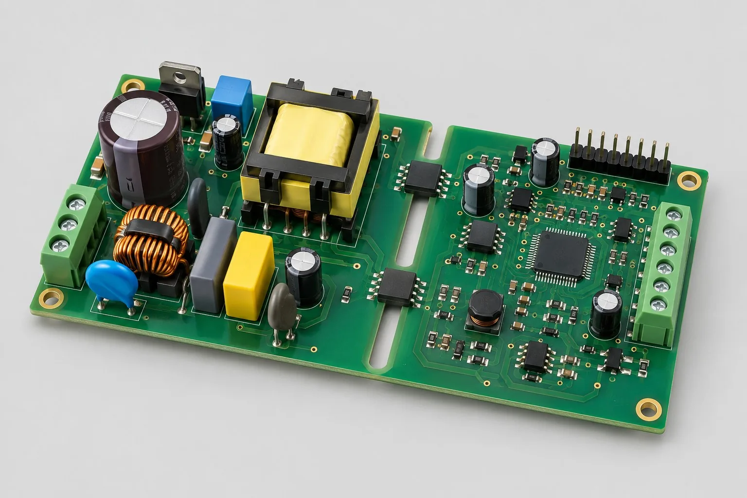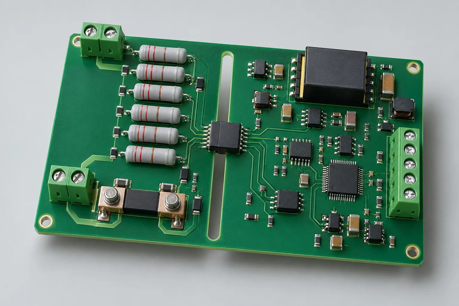
Engineering reference design · prototype validation pending
High-voltage sensing design: isolated bus voltage/current acquisition
Isolated bus designs transfer voltage/shunt-current through separate front ends to low-voltage measurement domains. The 400V DC is an example. Define ranges, insulation coordination, and failure outputs before dividers, isolated power, and calibration.
Custom development reference design. The parameters below are requirement configurations and design targets; validate product performance through agreed prototype tests.
| Functional Partition | Design and verification scope |
|---|---|
| High-voltage divider / current shunt | Define voltage-divider/current-shunt ranges, common mode, ratings, and protection separately; do not share unreviewed front ends. |
| Isolated Sampling Front End | Reference AMC1300-type small-range shunt parts and AMC1311-type high-impedance voltage parts; confirm actual numbers. |
| Low voltage ADC / MCU | Low-voltage ADC/MCUs receive isolated outputs; ranges, references, and calibration jointly control error. |
| Measurement / Alarm Interface | Choose analog differential/digital interfaces by need. Input faults need identifiable alarms, not normal low readings. |
| Isolated DC/DC Power Supply | Select isolated DC/DC and both supplies for front ends; check noise, undervoltage, and sequencing. |
| Full-layer isolation / failure check | Check isolation across layers, parts, terminals, and screws; record approved tests/failure outputs separately. |
How much does isolated high-voltage sensing design cost, and how are quotes calculated?
Costs vary with measurement/insulation. Dividers and shunts need different front ends; environments/failures alter layouts/tests. Separate range/error design, isolated power, prototypes, and agreed insulation/drift tests. Working voltage alone cannot set universal pricing.
Quotation terms depend on the approved files, quantity, material supply, tests and delivery requirements.
Prepare a structured RFQ or use the short inquiry form.
| Quotation Items | What services are included | What to Check When Comparing Quotes |
|---|---|---|
| Circuit and PCB Design | Voltage/current front ends, isolated power, and insulation coordination | Reusable portions of existing designs and circuit/mechanical changes |
| Software and Validation | Error and Failure Output Verification | Separately list ranges, error/drift, failure outputs, and insulation targets/conditions |
| Prototype Preparation | Bare PCB, BOM procurement, assembly, and agreed prototype quantity | Whether material/component revisions, prototype quantities, and test targets match |
| Subsequent Revision | Record new requirements separately from post-test corrections | How agreed changes, source files, and validation results are delivered |
Bus sampling: select voltage divider or shunt?
Voltage uses divider-type front ends; current uses shunts, with different isolator ranges. Define measurements first; do not mix circuits/quotes between approaches.
Can high-voltage spacing be estimated directly from voltage?
Insulation type, environment, pollution, and materials also matter. Establish applicable requirements/boundaries before spacing. Larger clearances alone do not replace coordination.
Do high-voltage sensing quotes include withstand-voltage/accuracy tests?
List ranges, error/drift, failure outputs, and insulation test targets/conditions separately. Chip ratings are not board results. Separate prototype verification from circuit design.
Isolated bus voltage/current sensing reference configuration
| Configuration Field | Reference Configurations/Selections | Basis and Status |
|---|---|---|
| Finished Product Function | High-side signal acquisition and isolated transmission | Design Objective |
| Voltage Target | 400V DC example requirement, not a rated safety commitment | Design Objective |
| Channel Configuration | Candidate 1 divider-voltage + 1 shunt-current channel | Design Objective |
| Isolation Architecture | Isolation amplifier/ADC selected by input range | Design Objective |
| Device Reference | AMC1300-type small-signal isolation amplifier for shunts | Design Objective |
| Voltage Channel | Divider chain + AMC1311-type high-impedance voltage isolator | Design Objective |
| Low-Voltage Interface | 3.3V MCU ADC/SPI or analog differential output | Design Objective |
| High-Side Power Supply | Isolated DC/DC; output voltage matches selected parts | Design Objective |
| Layer Candidate | 4 layer; isolation zone copper-free across all layers | Design Objective |
| Insulation Design | Defined by operating/transient voltage, pollution degree, CTI, and standards | Design Objective |
| Safety Structure | Review protection, fuses, discharge, and test safeguards together | Design Objective |
| Validation outputs | Error/drift, isolation, and fault test plans | Design Objective |
Voltage Divider/Shunt and Insulation Coordination
A small-range isolation amplifier for a shunt channel cannot directly serve a high-voltage divider channel. Select the two front ends separately.
Component isolation ratings are not board ratings. Assess traces, connectors, pollution, and assembly together.
Resistor chains distribute voltage/power; include component ratings and failures in safety analysis.
Design budget and trade-off examples
Check design targets with engineering calculations
At assumed divider ratio 200:1, 400V yields 2V at the divider output. With 2MΩ equivalent input resistance, total chain dissipation V²/R=0.08W.
Conditions and Scope of Application:This budgets only ratio/power, not resistor count, voltage ratings, clearances, or safety levels. Review input ranges, transients, errors, and insulation separately.
Replace examples with selected components and record margins; calculations support design choices, while prototype records support acceptance.
Isolated bus voltage/current sensing power and layout
- Define high-/low-voltage grounds; inspect isolation across copper, silkscreen/components, and screws.
- Distribute divider resistors; use Kelvin shunts to exclude main-path drops.
- Keep sensitive inputs away from DC/DC switching; protect terminals against accidental contact.
Isolation Sampling Board R&D Input
- Continuous, peak, transient voltages and measurement ranges
- Product standards, pollution degree, altitude, CTI, and isolation levels
- Shunts, supplies, mechanical protection, and laboratory conditions
If circuit files exist, provide editable schematics, PCB, BOM, and current issues, and agree on review or revision scope. If only functions are defined, freeze this page's inputs before selection and circuit development. Agree separately on control-software and external-application responsibilities, interfaces, and acceptance.
Isolation Sampling Board Phase Delivery
| Stage | Engineering Work for This Proposal | Reviewable Deliverables |
|---|---|---|
| Requirements and Design Freeze | Freeze continuous/transient voltages, both ranges, environment, standards, and tests | Functional/interface requirements, mechanical revision, acceptance conditions, and open items |
| Schematic and Component Selection | Design separate divider/shunt front ends, isolated power, and low-voltage measurement | Editable schematics, controlled BOM, footprint checks, and design calculations for these circuits |
| Layout and Routing | Implement all-layer keepouts, divider chains, Kelvin sensing, and touch protection | PCB source files, actual stackup/hole/net constraints, DRC, and assembly-dimension checks |
| Simulation/Calculation | Break down ratio/drift/isolation errors; review insulation, power, and failure outputs | Design calculations/models, input conditions, margins, and items awaiting measurement |
| Prototype and Software | Build isolated prototypes; integrate ADC/outputs, calibration, and faults | Manufacturing package, prototypes, front-end/isolation drawings, agreed firmware or analog interfaces, calibration, and safety records |
| Testing and Version Closure | Under approved plans calibrate drift/common mode; verify insulation and input/power faults | Procedures, wiring, raw results, and decisions for the prototype revision; include issue/change and limitation lists |
Bus error and failure output verification
- Controlled multipoint calibration and temperature drift
- Supply/common-mode effects on output error
- Approved-standard withstand-voltage/insulation/fault tests
- Open inputs, divider faults, and low-side power loss
Calibrate drift/common mode and verify insulation/input/supply faults under approved plans. Reports identify equipment, conditions, revisions, and criteria, recording passed/uncovered items.
Bus error and failure-output worksheet
The table turns isolated bus sensing into checks. Freeze samples, equipment, environment, and tolerances; link results to current raw records.
| Verification Object | Pre-Production Freeze | How to Test Prototypes in Practice | Delivery and Acceptance Records |
|---|---|---|---|
| Error Budget | Ranges, divider/shunts, isolated front ends, and error targets | Approved multipoint calibration, then temperature/common-mode comparisons | Deliver raw values, coefficients, and error breakdowns; accept voltage/current separately |
| Insulation Coordination | Operating voltage, category/environment, altitude, and standard revisions | Review all-layer keepouts, connectors, and enclosures before approved tests | Retain clearance/safety records; 400V references are not safety ratings |
| Failure Output | Divider opens/faults, low-voltage power loss, and allowable outputs | Simulate input/supply faults under control | Retain output/alarm timing; ensure faults cannot appear as normal low readings |
Manufacturing and assembly coordination for this design
- Include insulation slots, keepouts, edge/screw clearances, and declarations in Manufacturing Files.
- High-voltage fixtures use guards/interlocks; deliver test sequencing/discharge procedures.
Link design revisions to schematics, BOM, PCB, fabrication, and software documentation. When fabricators adjust stackup, materials, or holes, or Assembly parties propose substitutions, recheck critical electrical and test conditions together.
Common questions on purchasing and customization
How much does isolated high-voltage sensing design cost, and how are quotes calculated?
A project-specific quotation requires review of the available files, quantity, materials, requested tests, delivery destination, taxes, shipping, and trade terms. Complete development separately prices circuits, firmware, prototypes, and verification. Any formula on this page organizes cost inputs; it is not a quoted rate.View cost items, calculation conditions, and sources.
How should isolated sensing accuracy quotes be compared?
Align ranges, temperatures, calibration points, and error calculations. Review front ends, isolation, and sampling separately; ADC bits are not accuracy.
How should disconnections/failures be delivered for high-voltage sensing?
Define failure outputs/diagnostics. Record values/states under approved faults, avoiding abnormal results interpreted as normal zero.
How should sensing budgets quote voltage/current channels separately?
Separate example 400V DC divider-voltage/shunt-current front ends, listing isolation, power, errors/drift, and insulation. AMC1311 voltage and AMC1300 shunt approaches differ. Compare totals under equal environment/fault conditions.
Which boundaries need approval before high-voltage layout-only work?
Confirm ranges, isolation, operating/transient voltages, pollution, materials, and connectors, with keepouts/mechanical safety. Layout cannot choose product applicability for customers. Cheap routing without coordination inputs is not complete high-voltage design.
How should sensing hardware and diagnostic firmware divide work?
Hardware covers dividers/shunts/isolation/protection; firmware covers conversion/calibration/codes/outputs. Analog-only delivery may omit MCU code. ADC/SPI data requires sampling/status endpoints so faults are not normal zeros.
Which sources/evidence should isolated sensing deliver?
Deliver both channel calculations/devices, isolated power, keepouts, and mechanical boundaries. Commissioned code includes calibration/diagnostics. Retain error/drift, failure outputs, and approved insulation conditions separately. Chip ratings do not replace board results.
How should bus-target changes affect sensing revision fees?
Recheck divider dissipation, inputs, transients, supplies, insulation, and space. Conversion changes may be only part; budget hardware/high-voltage tests. New ratios cannot simply reuse old ranges/insulation records.
Can high-voltage sensing boards serve ordinary 4—20mA inputs?
Front ends/common-mode boundaries differ. Review transmitter power, loop headroom, and low-side sensing. Some isolated communication/diagnostic formats may remain, but high-voltage structures are not current-loop front ends. An isolator does not establish input compatibility.
How should RFQ files be prepared for isolated high-voltage sensing?
Initially describe functions, uses, and files. Quotes confirm continuous/peak/transient/ranges; standards/pollution/altitude/CTI/isolation; shunts/supplies/guards/lab conditions. Provide editable sources/BOM or fault-prototype revisions/reproduction records. List missing-data reviews to avoid differing assumptions.
How should isolated sensing prototype costs be compared by condition?
Fix quantities, revisions, equipment, and criteria. Separately check errors: frozen ranges/dividers/shunts/front ends/targets, calibration then temperature/common mode; insulation: fixed voltage/category/environment/altitude/standards, keepout/connector/enclosure review before tests; failures: fixed opens/faults/power loss/outputs, controlled simulation. Specify raw-data/closure delivery. One power-on pass is not full verification.
Compare related designs and plan the next step
Isolated power and control interface board design
Return to high voltage PCB design selection · Select solution by device function · Discuss your design requirements
Documentation Basis and Boundaries
Engineering reference | AMC1300 selection conditions and board verification: AMC1300 serves small shunt signals; AMC1311 serves voltage inputs. Isolation parameters do not establish board safety.
Engineering reference | AMC1311 isolated voltage sensing: dividers, power, and errors: Voltage sampling input architecture reference.