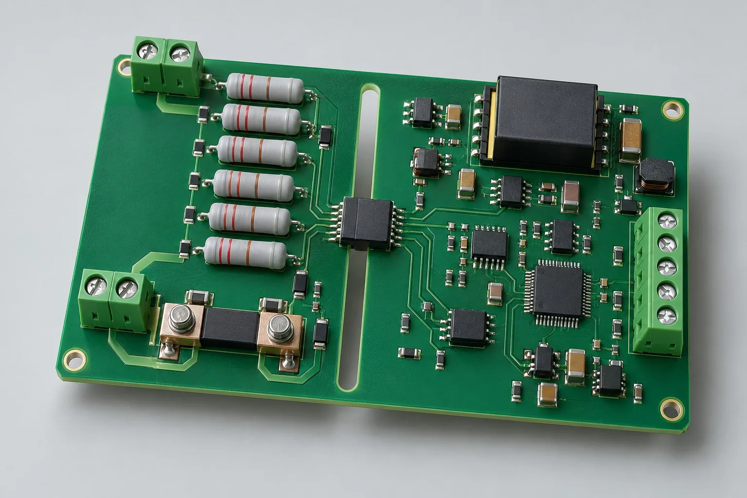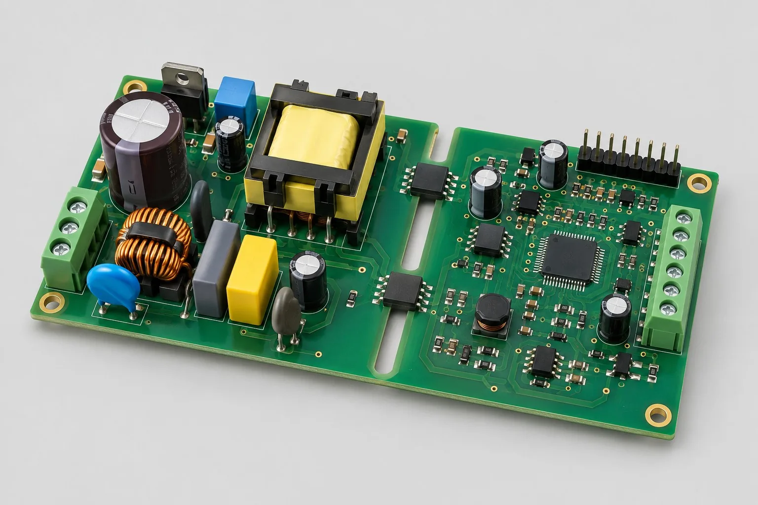
Engineering reference design · prototype validation pending
Isolated power controllers: PWM and isolated fault feedback
Isolated interfaces provide low-voltage PWM, feedback, and hardware shutdown for high-voltage stages. Develop with customer power boards, freezing topology, dead time, and sequencing. Accept controls separately from complete supply performance.
Custom development reference design. The parameters below are requirement configurations and design targets; validate product performance through agreed prototype tests.
| Functional Partition | Design and verification scope |
|---|---|
| Power system control input | Confirm topology, PWM, and drive requirements; separate 24V auxiliary and 400V bus boundaries. |
| Isolated Signal Channel | Select isolation channels by logic, domains, and maximum delay; calculate feedback/drive separately. |
| Low Voltage Control Interface | MCUs control/monitor; reset/disconnection defaults follow power-stage fail-safe tables. |
| Feedback / Fault Return | Select feedback/fault returns for actual front ends; hardware shutdown does not depend on normal software scheduling. |
| Isolated Power Supply | Distribute auxiliary power to isolated/nonisolated domains; review UVLO, startup, and missing-supply states together. |
| Shutdown / Timing Check | Measure protection input to actual drive output: dead time, delay, shutdown, and recovery, beyond MCU pins. |
How much does isolated controller design cost, and how are quotes calculated?
Quotes depend on PWM/fault/shutdown chains, not supply wattage. Interface-only work covers isolation, sequencing, and recovery; main topology, magnetics, and efficiency are separate. Distinguish controls from complete power development first.
Quotation terms depend on the approved files, quantity, material supply, tests and delivery requirements.
Prepare a structured RFQ or use the short inquiry form.
| Quotation Items | What services are included | What to Check When Comparing Quotes |
|---|---|---|
| Circuit and PCB Design | PWM/fault isolation interfaces and startup/shutdown logic | Reusable portions of existing designs and circuit/mechanical changes |
| Software and Validation | Power Sequencing and Anomaly Test | Control/fault-interface-only delivery focuses on timing and shutdown |
| Prototype Preparation | Bare PCB, BOM procurement, assembly, and agreed prototype quantity | Whether material/component revisions, prototype quantities, and test targets match |
| Subsequent Revision | Record new requirements separately from post-test corrections | How agreed changes, source files, and validation results are delivered |
How do isolated controllers and complete isolated supplies differ?
Controllers transfer PWM, faults, and shutdown states. Complete supplies also include topology, magnetics, efficiency, and cooling. Define interface versus full supply procurement; controller fees cannot estimate whole products.
Can digital isolators directly drive MOSFETs?
Signal isolation and gate drive differ. Check drive current/voltage/shutdown paths. Isolators do not eliminate device-specific drive design.
Do isolated controller quotes include efficiency verification?
Interface-only work focuses on timing/shutdown. Efficiency needs main stages, loads, and measurement conditions. Define full supply development/verification separately.
PWM and isolated fault-feedback reference configuration
| Configuration Field | Reference Configurations/Selections | Basis and Status |
|---|---|---|
| Finished Product Function | Power board control, isolated feedback, and monitoring | Design Objective |
| Application Target | Example supporting requirement for 400V DC bus systems | Design Objective |
| On-Board Power Supply | 24V auxiliary input → isolated/nonisolated low-voltage domains | Design Objective |
| Control Output | 2 candidate PWM channels; topology defines drive endpoints | Design Objective |
| Feedback Interface | Isolated voltage/current sensing or digital interfaces | Design Objective |
| Main Controller Configuration | MCU + digital isolators + isolated power | Design Objective |
| Protection Input | Overcurrent/overtemperature/fault hardware shutdown | Design Objective |
| Communication Interface | Optional RS485/CAN host monitoring | Design Objective |
| Layer Candidate | 4–6 layers; no copper crossing isolation zones | Design Objective |
| Timing Target | Dead time/delay defined by topology, without universal values | Design Objective |
| Structural Boundary | Power-board pinouts, isolation, and mistake-proof connections | Design Objective |
| Validation outputs | PWM/fault timing, isolated power, and safety tests | Design Objective |
Control interface and main power stage boundary
A low-voltage control board is not a complete 400V power supply. Main power devices, magnetic components, and the closed loop jointly determine performance.
Hardware fault shutdown precedes software tasks. Define reset/disconnection output-off strategies separately.
Include isolator delays/channel skew in dead-time budgets; MCU waveforms alone are insufficient.
Design budget and trade-off examples
Check design targets with engineering calculations
At assumed controller-to-isolator delay 100ns and downstream response 200ns, one-way budget is 300ns. Bidirectional feedback also includes the other channel.
Conditions and Scope of Application:These illustrative delays are not device promises. Use maximum conditions and measure shutdown, missing supplies, and startup sequencing.
Replace examples with selected components and record margins; calculations support design choices, while prototype records support acceptance.
PWM/isolated fault-feedback power and layout
- Arrange isolators/interconnects by domain; separate power-side/controller reference grounds.
- Short, testable shutdown paths; feedback filters must not add unreviewed protection delay.
- Keep DC/DC heat/noise away from sensing; inspect isolation on all copper layers.
Power control interface R&D input
- Topology, switching frequency, dead time, and faults
- Operating/transient voltage, isolation, and standards
- Power connectors, sequencing, and closed-loop software scope
If circuit files exist, provide editable schematics, PCB, BOM, and current issues, and agree on review or revision scope. If only functions are defined, freeze this page's inputs before selection and circuit development. Agree separately on control-software and external-application responsibilities, interfaces, and acceptance.
Power control interface phase delivery
| Stage | Engineering Work for This Proposal | Reviewable Deliverables |
|---|---|---|
| Requirements and Design Freeze | Freeze topology, PWM/dead time, fault timing, isolation, and pinouts | Functional/interface requirements, mechanical revision, acceptance conditions, and open items |
| Schematic and Component Selection | Design MCU, digital isolation, front ends, isolated supplies, and hardware shutdown | Editable schematics, controlled BOM, footprint checks, and design calculations for these circuits |
| Layout and Routing | Arrange domains/short shutdown; check connectors and all-layer keepouts | PCB source files, actual stackup/hole/net constraints, DRC, and assembly-dimension checks |
| Simulation/Calculation | Budget maximum delays/skew, auxiliary heat, and failure states | Design calculations/models, input conditions, margins, and items awaiting measurement |
| Prototype and Software | Build interfaces; integrate PWM/feedback/faults before planned power-board connection | Manufacturing package, interfaces, agreed PWM/monitoring firmware, states/pinouts, programming/recovery, and joint-test notes |
| Testing and Version Closure | Measure actual drive dead time/shutdown and undervoltage; close board/system issues separately | Procedures, wiring, raw results, and decisions for the prototype revision; include issue/change and limitation lists |
Isolated shutdown and power sequencing verification
- Actual dead time/skew after isolation/drive chains
- Overcurrent/temperature input-to-shutdown timing
- Auxiliary undervoltage, reset, and lost communication
- Isolated supply heating, insulation, and fault plans
Measure drive timing/shutdown/undervoltage; close board/system issues separately. Reports identify equipment, conditions, revisions, and criteria, recording passed/uncovered items.
Isolated shutdown and power-sequence worksheet
The table turns PWM/isolated feedback into checks. Freeze samples, equipment, environment, and tolerances; link results to current raw records.
| Verification Object | Pre-Production Freeze | How to Test Prototypes in Practice | Delivery and Acceptance Records |
|---|---|---|---|
| Shutdown Link | PWM modes, dead time, isolation delay, and protection timing | Measure propagation/shutdown from current/temperature inputs to drives | Deliver waveforms/budgets; typical isolator values do not replace complete chains |
| Auxiliary Power Supply | Startup sequence, UVLO thresholds, and default drive states | Simulate undervoltage, reset, and communication loss | Retain startup/shutdown states; accept against power-stage fail-safe tables |
| System Boundary | Main power board, topology, isolated supplies, and prototype wiring | Verify interfaces first, then integrate power boards under joint plans | Deliver board/system reports separately; controls do not establish complete 400V supply performance |
Manufacturing and assembly coordination for this design
- Include pinouts, mistake-proofing, and domain labels in assembly files.
- Separate fixture domains; trace software/shutdown logic per board.
Link design revisions to schematics, BOM, PCB, fabrication, and software documentation. When fabricators adjust stackup, materials, or holes, or Assembly parties propose substitutions, recheck critical electrical and test conditions together.
Common questions on purchasing and customization
How much does isolated controller design cost, and how are quotes calculated?
A project-specific quotation requires review of the available files, quantity, materials, requested tests, delivery destination, taxes, shipping, and trade terms. Complete development separately prices circuits, firmware, prototypes, and verification. Any formula on this page organizes cost inputs; it is not a quoted rate.View cost items, calculation conditions, and sources.
How to accept isolated control board undervoltage?
Test undervoltage/startup/recovery by sequence, recording PWM/feedback with explicit shutdown criteria.
How should hardware/software shutdown be compared?
Define triggers/chains separately and check stalled-software states. Itemize actual circuits/tests.
How should isolated project budgets stay within controller scope?
List 24V auxiliary, dual PWM candidates, isolation, and monitoring, separating main topology/magnetics/efficiency. Compare by pinouts/shutdown, not inferred 400V or wattage-based fees.
Which power-side files are needed for isolated layout-only work?
Provide frequency/dead time, drive inputs, delay budgets, fault returns, defaults, and domains. Layout implements 4–6-layer returns/keepouts. Without gate drives/topology/magnetics, do not assume digital isolators provide them.
How should PWM firmware and hardware shutdown be agreed?
Firmware handles modes/PWM/monitoring; hardware chains shut down under agreed conditions. Define triggers/recovery separately. Test stalls, undervoltage, and startup even with existing code. Software PWM stopping does not replace hardware in every fault.
Which timing/recovery files should controller sources include?
Agree isolator/supply revisions, pinouts, PWM/fault sources, and dead-time/mode/recovery settings. Retain startup/undervoltage/fault/shutdown waveforms and both supplies to reassess delays/defaults after power-board changes.
How should isolator substitutions change development estimates?
Check directions/defaults/delays/skew/power/isolation, then circuit/layout changes. Even pin-compatible parts need timing/power-loss regression. Include parameter review/interface tests, not replacement alone.
Can controllers directly serve another power topology?
PWM, dead time, faults, and drives may change. Rebuild timing/fail-safe tables. Retain communication/tools where possible; separately price interfaces/system tests. Dual PWM candidates must match actual topology, not arbitrary drives.
How should RFQ files be prepared for isolated power controllers?
Initially describe functions, uses, and files. Quotes confirm topology/frequency/dead time/faults; voltages/isolation/standards; connectors/sequences/closed-loop software. Provide editable sources/BOM or fault-prototype revisions/reproduction records. List missing-data reviews to avoid differing assumptions.
How should isolated controller verification costs be compared by condition?
Fix quantities, revisions, equipment, and criteria. Separately check shutdown: fixed modes/dead time/delays/protection timing, input-to-drive measurements; auxiliary power: fixed sequences/UVLO/defaults, simulated undervoltage/reset/disconnection; boundaries: fixed stages/topology/supplies/wiring, interface tests before joint power tests. Specify raw-data/closure delivery. One power-on pass is not full verification.
Compare related designs and plan the next step
High voltage bus isolation sampling board design solution
Return to high voltage PCB design selection · Select solution by device function · Discuss your design requirements
Documentation Basis and Boundaries
Engineering reference | AMC1300 selection conditions and board verification: AMC1300 applies only to selected shunt feedback. Use corresponding manuals for digital isolation, PWM, and isolated supplies.