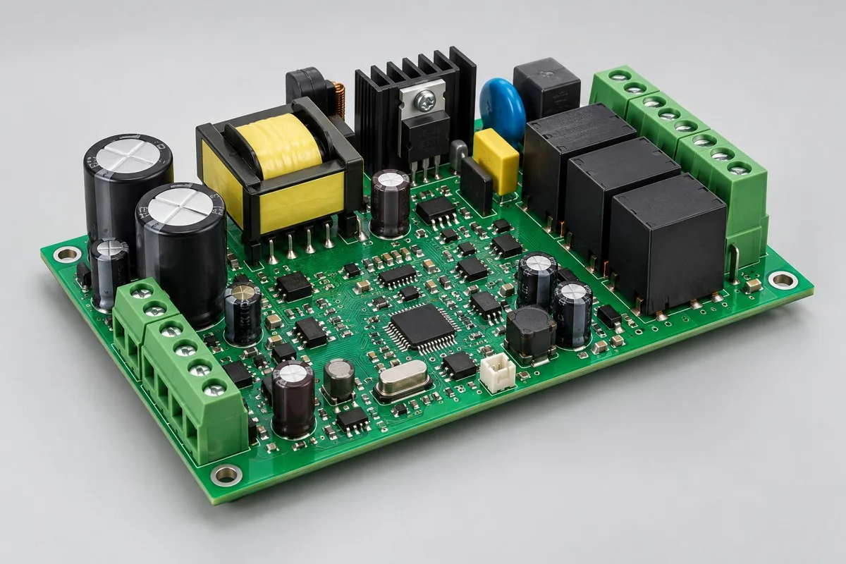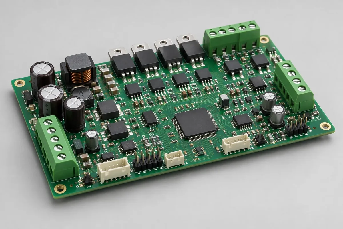
Engineering Reference Configuration
Motor driver board assembly: assembly configuration and test deliverables
The following adjustable engineering configurations support material, functional, and process review; they are not stocked models or commitments to current production-line capabilities. Approved fabrication documentation and order acceptance requirements govern.
Mixed-technology motor driver board assembly supports contract manufacturing and procurement review for two motors/actuators and feedback control. First confirm MCU + drivers + power components + current sensing, through-hole power terminals, Hall/limit inputs, maintenance serial ports, and 4/6-layer FR-4 with separate power-loop/logic regions. Then compare SMT → through-hole soldering → thermal assembly → loaded/protection testing scope and acceptance costs for phase sequence/feedback, loads, temperature rise, current limiting, and shutdown. This page separates driver boards/assemblies + load parameters + test results from low-voltage dual-channel references with operating current established by complete-system verification, helping determine whether quotations cover the actual application. Quotation documentation reference:BOM · bare board · material supply
Reference specification and configuration options
| Options | Reference Configuration |
|---|---|
| Power and Logic Domains | 24V low voltage input reference |
| Functional Module | Two motors/actuators and feedback control |
| Core Components/Architecture | MCU + drivers + power components + current sensing |
| Interface and Channels | Through-hole power terminals; Hall/limit inputs; maintenance serial port |
| Board Layers and Material Options | 4/6-layer FR-4; separate power-loop/logic regions |
| Component types | SMD control + TO/through-hole power components + terminals/capacitors |
| Assembly Route | SMT → through-hole soldering → thermal assembly → loaded/protection testing |
| Material Supply Scope | Specified power components/motors/thermal structures |
| Firmware and Parameters | Action, current limiting, feedback and fault recovery |
| Test Focus | Phase sequence/feedback, loads, temperature rise, current limiting, and shutdown |
| Deliverables | Driver board/assembly + load parameters + test results |
| Configuration Limits/Options | Low-voltage dual-channel reference; operating current established by complete-system verification |
How much does mixed-technology motor driver board assembly cost, and what is included?
Dual-channel power components, through-hole capacitors, terminals, and thermal structures determine mixed motor-board costs. Itemize lead forming, soldering, thermal assembly, and dual-channel loaded/protection testing. Actual operating currents and motor-specific test conditions affect labor; two channels alone cannot determine prices.
Quotation terms depend on the approved files, quantity, material supply, tests and delivery requirements.
Prepare a structured RFQ or use the short inquiry form.
| Cost Item | Scope for This Configuration | Billing frequency and work scope | Procurement Verification |
|---|---|---|---|
| Bare PCB and core components | MCU + drivers + power components + current sensing; 4/6-layer FR-4; separate power-loop/logic regions | Price according to actual bare-board/component purchase quantities; authorize critical components and substitutions individually | Specified power components/motors/thermal structures |
| Placement and Post-Assembly | SMT → through-hole soldering → thermal assembly → loaded/protection testing | Feeder/program setup per lot; assembly priced per board, joint, or process as agreed, with counting rules specified | SMD control + TO/through-hole power components + terminals/capacitors |
| Manufacturing Preparation | Review stencils, first articles, and support tooling against the actual assembly route | New stencils/carriers may be separate one-time charges; verify panelization, revision, and condition before reuse | Reduced quantities do not automatically eliminate first-article or feeder setup |
| Functional Support | Phase sequence/feedback, loads, temperature rise, current limiting, and shutdown | Itemize test-method/fixture/script setup; agree execution charges per board, channel, or test duration | Separate supporting development from execution records for each board |
| Software and Parameters | Action, current limiting, feedback and fault recovery | When firmware exists, distinguish file programming/verification from software development; omit programming without a firmware revision | Customer-approved files, parameters, and readback rules determine scope |
| Delivery and Change | Driver board/assembly + load parameters + test results; low-voltage dual-channel reference; operating current established by complete-system verification | Price accessories, retesting, and revision changes by approved work items; do not prefill fixed rates | Check BOM, tooling, programs, and acceptance revisions before reorders |
How should all-SMT and mixed SMT and Through-Hole motor boards be compared?
All-SMT designs reduce through-hole work but require suitable structures and thermal paths. Through-hole power components simplify some mechanical installations but add soldering and stress management. Select complete process routes by motor loads, installation, and maintenance.
| Comparison Metric | Current Conditions | Factors Influencing Procurement Decision |
|---|---|---|
| Manufacturing Delivery | SMT → through-hole soldering → thermal assembly → loaded/protection testing | Produce boards/assemblies per BOM and assembly drawings; this does not establish that every system function passes |
| Functional Acceptance | Phase sequence/feedback, loads, temperature rise, current limiting, and shutdown | Compare unit prices after defining test stimuli, limits, accessories, and records; review missing test inputs first |
| Configuration Options | Through-hole power terminals; Hall/limit inputs; maintenance serial port; 4/6-layer FR-4; separate power-loop/logic regions | Confirm circuit/program compatibility before reviewing assembly and test costs for interface, stackup, or component changes |
| Delivery Scope | Low-voltage dual-channel reference; operating current established by complete-system verification | Complete-system accessories, application development, and project verification are not automatically included in board assembly |
What matters when two channels use different motors?
Check startup, operating, and fault currents, feedback, and control parameters separately; do not assume identical loads. Test both channels together after thermal assemblies are installed. Increased capacitance also requires startup-surge review.
- First list required two-motor/actuator feedback control, distinguishing build-to-print manufacturing, configuration adjustments, and new-function development.
- Then freeze complete part numbers for MCU + drivers + power components + current sensing, through-hole power terminals, Hall/limit inputs, maintenance serial ports, and 4/6-layer FR-4 with separate power-loop/logic regions. Separate customer-supplied and sourced materials using specified power components/motors/thermal structures.
- Use first articles to check SMT → through-hole soldering → thermal assembly → loaded/protection testing, plus actuation, current limiting, feedback, and fault recovery. If only program files are supplied, agree programming verification first; development requires separate review.
- Convert phase sequence/feedback, loads, temperature rise, current limiting, and shutdown into acceptance items with stimuli, limits, and records; specify fixture ownership, per-board execution, and post-repair retesting.
- Finally confirm driver boards/assemblies + load parameters + test results and low-voltage dual-channel references with operating current established by complete-system verification. Compare totals using identical quantities, accessories, and test scope, then freeze the order revision.
Applicable uses and situations requiring separate review
Dual-channel actuator drives, low-voltage motor equipment.
High-speed servos, extremely dense multiaxis systems, and high-power inverters cannot directly adopt this configuration. Continuous-current claims based only on power-component maximum ratings ignore driver, copper-path, terminal, and thermal limits.
Assembly Challenges for This Product
Power-component insertion, lead forming, and thermal installation introduce mechanical stress. Define assembly sequence and fixture alignment first. Terminal post-soldering heat must not damage nearby driver/sensing parts; final loaded tests occur after thermal assembly is complete.
Structural, thermal, and configuration trade-offs
Large through-hole components improve mechanical-installation flexibility but increase soldering thermal mass. All-SMT reduces labor but requires structural and thermal redesign. Larger capacitors may reduce some fluctuations while increasing startup surge and fastening requirements.
Product-specific test matrix
| Test stage | Inspection/Functional Methods | Acceptance Record |
|---|---|---|
| Control Feedback | Simulate actuation, Hall/limit inputs, and direction per channel | Mapping, Parameter, and Action |
| Load thermal | Record current and thermal measurement points under approved load cycles | Operating condition, hotspot, and stable state |
| Fault Protection | Current limiting/shutdown under abnormal inputs or restricted-load conditions | Action, recovery, and program version |
Defect Handling and Acceptance
Assess poor power-lead joints, missing insulation, reversed feedback, and crossed dual-channel wiring separately. Acceptance includes simultaneous operation; single-channel no-load tests do not establish shared power/thermal performance.
Mixed-technology motor driver PCB assembly: material supply and revision management
Lock matched MOSFET/driver models. Customer-supplied motors, heat-dissipation parts, and harnesses require mechanical/load conditions. Reassess drive losses, current limiting, and process heat resistance for substitutions.
Prototyping vs. Production Differences
Samples verify thermal/protection parameters. Production fixes fixtures, heat-sink torque, and channel error prevention. After power-stage repairs, recheck sensing and simultaneous dual-channel results.
Delivery Configuration
Driver board/assembly + load parameters + test results. Low-voltage dual-channel reference; operating current established by complete-system verification.
Convert this configuration into a reviewable order
For mixed-assembly motor driver board orders, check BOM, quantity, material supply, and the conditions below. Add pick-and-place files, DNP lists, and assembly drawings for SMT. For programming, provide actuation, current-limiting, feedback, and fault-recovery files with programming rules and verification requirements. Review costs separately for materials, SMT → through-hole soldering → thermal assembly → loaded/protection testing, required stencils/feeder setup, support carriers, and test resources. Documentation changes require renewed revision approval; agree delivery milestones after material readiness and scheduling confirmation.
| Required project inputs | Engineering Decisions Affected | Records/delivery as agreed in the order |
|---|---|---|
| Two-Channel Drive Combination | Provide both actuators, feedback sensors, and simultaneous operating modes to determine loads and thermal resources. | Record current, temperature rise, and fault responses during separate and simultaneous operation. |
| Power-component installation and thermal assembly | Provide heat sinks, insulating pads, and torque requirements. | Check insulation/fastening on post-installed first articles and retest drivers instead of inspecting only post-reflow boards. |
Motor driver board mixed assembly processing common issues
How much does mixed-technology motor driver board assembly cost, and what is included?
For standard placement, first calculate board quantity × billable points per board × price per point + setup fee. A project-specific quotation requires review of the available files, quantity, materials, requested tests, delivery destination, taxes, shipping, and trade terms. This is a placement-only reference; bare PCBs, materials, and testing are charged separately. Any formula on this page organizes cost inputs; it is not a quoted rate.View cost items, calculation conditions, and sources.
How should all-SMT and mixed SMT and Through-Hole motor boards be compared?
All-SMT designs reduce through-hole work but require suitable structures and thermal paths. Through-hole power components simplify some mechanical installations but add soldering and stress management. Select complete process routes by motor loads, installation, and maintenance.
What matters when two channels use different motors?
Check startup, operating, and fault currents, feedback, and control parameters separately; do not assume identical loads. Test both channels together after thermal assemblies are installed. Increased capacitance also requires startup-surge review.
Does mixed motor-board assembly include heat-sink installation?
List heat sinks, insulation, fasteners, and assembly sequences in mechanical BOMs. Board quotations covering only power-component soldering do not include complete thermal interfaces; loaded-test records must match actual thermal revisions.
Can a two-channel motor board be accepted by testing only one channel?
Each channel's components, terminals, and feedback have independent failure points. Define per-board release scope in control plans. Prototype verification covers both channels and combined states; the other channel does not pass automatically.
How much can terminal and capacitor substitutions save on mixed motor boards?
Check currents, startup surges, fastening, and soldering conditions first; new parts may change processes and verification. Do not specify savings percentages before loads and revisions are confirmed, avoiding lower material prices that increase rework.
What parameters should dual-channel motor driver delivery records include?
Record both motor configurations, feedback, current limiting, and fault recovery, linked to thermal components and load results. Specify differing channel conditions separately; one channel's result cannot represent the complete assembly.
How should control-feedback testing be included in mixed motor-board procurement acceptance?
The reference method simulates actuation, Hall/limit inputs, and direction per channel. Records include mappings, parameters, and actions. Supply test inputs, applicable configurations, and acceptance limits with the inquiry, then agree first-article verification and per-board execution scope. Price test-resource setup separately from each execution. Methods can be reviewed before limits are available, but completing an operation does not establish specification compliance.
How should loaded thermal testing be included in mixed motor-board procurement acceptance?
The reference method records current and thermal measurement points under approved load cycles. Records include operating conditions, hot spots, and steady states. Supply test inputs, applicable configurations, and acceptance limits with the inquiry, then agree first-article verification and per-board execution scope. Price test-resource setup separately from each execution. Methods can be reviewed before limits are available, but completing an operation does not establish specification compliance.
How should fault-protection testing be included in mixed motor-board procurement acceptance?
The reference method checks current limiting/shutdown under abnormal inputs or restricted-load conditions. Records include actions, recovery, and program revisions. Supply test inputs, applicable configurations, and acceptance limits with the inquiry, then agree first-article verification and per-board execution scope. Price test-resource setup separately from each execution. Methods can be reviewed before limits are available, but completing an operation does not establish specification compliance.
How are programming and development priced separately when customers supply mixed motor-board software?
Controlled content comprises actuation, current limiting, feedback, and fault recovery. Programming customer-approved files, loading parameters, and verifying readback are manufacturing operations; new logic, interface adaptation, or algorithm changes require development review. Separately price resource setup, per-board programming, verification, and failure handling. Programming included does not imply application development included.
Must first-article, stencil, and feeder-setup charges be recalculated for mixed motor-board reorders?
The route is SMT → through-hole soldering → thermal assembly → loaded/protection testing. Check stencils and panelization for SMT, and supports/assembly methods for through-hole or later-installed parts. Agree feeder setup and first articles for the current lot; reuse existing tooling only when revision, locations, and condition match. After changing SMD control components, TO/through-hole power components, terminals/capacitors, or interfaces, review tooling and impacts on phase sequence/feedback, loads, temperature rise, current limiting, and shutdown before confirming repeat charges.
How should total mixed motor-board assembly costs be compared when critical components are customer-supplied and others sourced?
Create a procurement-responsibility table using specified power components/motors/thermal structures. Confirm complete part numbers, quantities, packaging, and remaining-material rules with deliveries. Customer supply changes only procurement boundaries; SMT → through-hole soldering → thermal assembly → loaded/protection testing and phase sequence/feedback, loads, temperature rise, current limiting, and shutdown remain actual work. Approve shortage, substitution, or lot-change impacts first; do not directly compare consigned assembly unit prices with material-inclusive assembly totals.
What requires retesting after mixed motor-board repairs or repeat orders?
Select retests by change impact. Original acceptance covers phase sequence/feedback, loads, temperature rise, current limiting, and shutdown; shipping records include driver boards/assemblies + load parameters + test results. Repairs affecting power, interfaces, critical analog circuits, or software revisions require related tests, beyond repaired joints. Repeat orders must align with original BOMs, parameters, and test resources. Agree retest charges by approved items and actual quantities; do not assume free service or fixed turnaround.
Compare Other Products in This Category
- Mixed assembly industrial power control board: SMT control and large thermal mass through-hole.
Return to mixed SMT and Through-Hole assembly configuration comparison · Component Supply and Procurement · Testing and Delivery Scope
Material and Process Reference
- Engineering reference | SMT packages and assembly methods: pads, stencils, and thermal processes: a package/assembly method index only; not evidence that the product configurations on this page are models produced by KFPCBA
- Engineering reference | Soldering processes and defect isolation: wetting, residues, and solder oxidation: a reference entry for soldering, residues, and defect isolation methods only. Verify this page's soldering routes against specific materials/components