Engineering Selection Reference
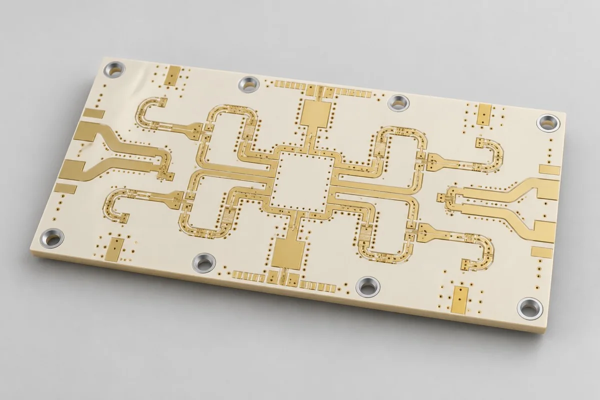
TMM10i PCB: TMM10i resonant filter fabrication review
Review TMM10i filters against current drawings. Bare TMM10i high-Dk resonators need bands, trimming strategies, critical trace/gap drawings. Thick dielectric has distinct port geometry; high Dk does not permit uniform scaling. Deliver dimensions/material revisions; validate first-sample center frequency/bandwidth by same-fixture VNA.
Define bare TMM10i prototyping/production scope first. Please provide Gerber data, drill files, board outline, and layer stackup, materials/process, quantity, acceptance. Thermoset ceramic/thicker dielectric serve resonators, unlike RO3010 antennas
For TMM10i resonant filter review, check TMM10i 1.270mm dielectric/coupling gaps first; add resonator dimensions, tuning copper, model revisions. Map design targets and inspection methods in the specifications and fabrication-input tables below.
Why select this structure for high Dk resonant boards
TMM10i reference boards suit microwave filters using high Dk to shorten resonators and thicker cores for specified coupling. The 1.270mm dielectric and resonant traces/gaps jointly define the structure, unlike thin RO3010 antenna space trade-offs.
What mainly determines TMM10i microwave prototype pricing?
1.270mm TMM10i cores, resonant/coupling geometry, holes, immersion silver, and unmasked windows comprise costs. Filter curves add connectors, fixtures, VNA bands; buying high-Dk material does not deliver filter performance. Align outline, bands, critical-gap tolerances before prototype/production comparison.
Quotation terms depend on the approved files, quantity, material supply, tests and delivery requirements.
Prepare a structured RFQ or use the short inquiry form.
Enter the following items in one itemized quotation: specify cost units and tax/shipping basis, with separate columns for first orders and same-revision repeat orders. The table is a procurement breakdown method, not a ready-made price list; reference specifications require approval against current fabrication drawings.
| Quotation items and scope | Inputs to confirm for this configuration | Same-revision reorders and changes |
|---|---|---|
| Materials/fabrication, quoted per batch or accepted board | Rogers TMM10i; 2 layers; base/finished copper target 35µm/35µm | Recurs on repeat orders; material, layer-order, or copper-weight changes require requotation |
| Holes and forming, per approved hole table | Ø0.40mm finished holes; resonators retain only modeled holes | Repeat orders use same revisions; review process effects of sensitive resonator changes |
| Surface finish/packaging, noting areas and batches | Immersion silver; unmasked resonator window | Incurred by actual batch; confirm packaging, storage conditions, and surface-finish substitutions separately |
| Engineering/tooling preparation, identifying one-time or per-batch charges | Resonator-sensitive dimensions: provide TMM10i patterns, target bands, trimming strategy; decide retained tuning copper. | Verify file revisions, ownership, and storage condition before reusing old tooling; do not assume reuse is free |
| Structural/special inspections, identifying coupons, hole groups, or samples | Record measured resonant lengths/gaps and fixtures to avoid blaming frequency shifts on material. Retain simulation-parameter sources and approved thickness revisions. | List initial prototype validation and per-batch sampling separately; quote per-board requirements separately rather than assuming everything is completed once |
| Delivery scope, reports, and accepted quantity | Bare resonant-filter PCB, critical coupling dimensions, batches, approved simulation geometry; optional same-panel filter test structures. | Retain revision links and batch records on repeat orders; list component assembly, firmware, and complete-unit testing separately |
How do TMM10i and RO3010 high-Dk boards differ?
This thicker TMM10i targets compact resonant filtering; RO3010 targets patches/mounting space. Materials, dielectric thickness, geometry differ; similar Dk does not establish same-outline substitution. Define resonator shortening versus antenna miniaturization before ports/bandwidth.
| Comparison Dimension | TMM10i PCB fabrication | RO3010 antenna PCB fabrication |
|---|---|---|
| Material and Grade | Rogers TMM10i | Rogers RO3010 |
| Layer Count and Structure | 2 Layer | 2 Layer |
| Hole Structure and Dimensions | Ø0.40mm finished holes; resonators retain only modeled holes | Ø0.30mm feed through holes; via-fence dimensions coordinated with radiating structure |
| Application | High-Dk microwave resonators; compact bandpass filters | Space-constrained patch antennas; compact resonant circuits |
How should high-Dk filter coupling gaps and thickness be selected?
Center/passband/stopband targets define length/coupling, modeled with 1.270mm dielectric. Give critical gaps/ends independent tolerances; resolve material changes. Minimum 0.20mm routing references do not apply to all coupling gaps or establish bandwidth.
| Review step | Project inputs | Reviewable output |
|---|---|---|
| 1 Define use and scope | Provide TMM10i patterns, bands, trimming strategy; decide retained tuning copper. | Record measured lengths/gaps and fixtures to avoid misattributed material frequency shifts. |
| 2 Confirm structural requirements | Define manufacturer methods/design models; recalculate resonators after substitutions. | Retain simulation-parameter sources and approved thickness revisions. |
| 3 Match signal nets to fabrication targets | 50Ω ports; resonant design/VNA acceptance for filter sections | Provide nets/layer pairs/validation; review Ø0.40mm finished holes and model-only resonator holes |
| 4 Confirm quotation and approved revision | Rogers TMM10i; 1.34mm target excluding mask; immersion silver; unmasked resonator window | Request quotations using material/pattern/inspection lists at the same revision; list unapproved substitutions as separate alternatives rather than including them in the baseline quotation |
High-Dk resonant board manufacturing specifications
| Specification | Reference configuration or target |
|---|---|
| Material and Grade | Rogers TMM10i |
| Layer Count and Structure | 2 Layer |
| Total Board Thickness | 1.34mm target excluding solder mask |
| Dielectric thickness and interlayer relationship | 1.270mm Core Board |
| Base Copper and Finished Copper | Base copper 35µm/finished copper target 35µm |
| Hole Structure and Dimensions | Ø0.40mm finished holes; resonators retain only modeled holes |
| Trace Width and Spacing | 0.20/0.20mm reference design; label resonant gaps separately |
| Impedance Target and Measurement Methods | 50Ω ports; resonant design/VNA acceptance for filter sections |
| Surface Finish | Immersion silver; unmasked resonator window |
| Manufacturer material data | TMM10i: process Dk 9.80±0.245, design Dk 9.9; Df 0.0020 (10GHz, manufacturer typical) |
| Application | High-Dk microwave resonators; compact bandpass filters |
| Deliverables | Bare resonant-filter PCB, critical coupling dimensions, batches, approved simulation geometry; optional same-panel filter test structures. |
High Dk resonant board layer sequence and hole structure
The following shows functional layer order/material structure for this reference configuration, not a production stackup drawing; do not infer thickness from graphic proportions. Match copper-layer numbering to via layer pairs item by item in approved fabrication files.
| Top to Bottom | Layer Responsibilities/Structure |
|---|---|
| L1 | Resonant/coupling structure |
| L2 | Resonant Reference Ground |
Holes: Ø0.40mm finished; resonators retain modeled holes only
TMM10i dielectric and loss model
TMM10i process Dk supports comparison; transmission/resonator models use appropriate-frequency/method design Dk. Freeze purchased thickness/foil/finish; return first-article geometry for review. Df is only a loss-budget input.
Trade-offs between sensitive resonant geometry and material systems
High Dk increases fabrication sensitivity; matching/coupling need full-wave models. TMM10i is a special thermoset ceramic system; ordinary FR4 drilling/etching experience does not establish reliability. Check flammability boundaries against system requirements too.
Resonant ends, ground holes, connector datums: fabrication inspection
Dimension resonant ends, gaps, ground holes separately; minimum-spacing metrics do not replace critical tolerances. Thick-dielectric ports need fixed reference planes. Cutting/drilling must preserve resonator edges; model finish thickness.
Center/passband/stopband VNA: acceptance
Measure center frequency, insertion/return loss, stopband with reproducible fixture positions/de-embedding. Typical material Dk is a model starting point; first-sample feedback can adjust geometry. Production uses approved revisions/sampling conditions.
High-Dk resonant board delivery scope
Applications: high-Dk microwave resonators; compact bandpass filters.
Bare resonant-filter PCB, critical coupling dimensions, batches, approved simulation geometry; optional same-panel filter test structures.
Resonator dimensions, tuning copper, model revisions: RFQ inputs
Submit dimensions/tuning/model revisions to turn targets into inspectable drawings. Inputs define pattern/material/structural checks; freeze quotations with approved drawings.
| Required project inputs | Engineering Decisions Affected | Records/delivery as agreed in the order |
|---|---|---|
| Resonator size sensitive items | Provide TMM10i patterns, bands, trimming strategy; decide retained tuning copper. | Record measured lengths/gaps and fixtures to avoid misattributed material frequency shifts. |
| High Dk Model | Define manufacturer methods/design models; recalculate resonators after substitutions. | Retain simulation-parameter sources and approved thickness revisions. |
TMM10i PCB pricing, selection, procurement FAQ
What mainly determines TMM10i microwave prototype pricing?
The complete budget is materials/base fabrication + excluded profiling + specified inspection + taxes and shipping, divided by the delivered board quantity. A project-specific quotation requires review of the available files, quantity, materials, requested tests, delivery destination, taxes, shipping, and trade terms. These hypothetical amounts do not represent current market pricing for this product. Any formula on this page organizes cost inputs; it is not a quoted rate.View cost items, calculation conditions, and sources.
How do TMM10i and RO3010 high-Dk boards differ?
Thicker TMM10i serves compact resonant filters; RO3010 pages concern high-Dk patches. Material, thickness, geometry differ; similar Dk does not allow equal-outline substitution. Define resonator/antenna tasks before bandwidth/ports. View Specific Comparison Basis
How should high-Dk filter coupling gaps and thickness be selected?
Bands/passband/stopband define length/coupling, calculated with actual dielectric. Critical gaps/ends need separate tolerances; 0.20mm routing does not replace coupling design. Recalculate/validate material or thickness changes. View Specific Comparison Basis
Is high-Dk TMM10i always cheaper?
High Dk offers size trade-offs, but procurement, geometry, testing also cost. Compare area/process/validation for identical filter objectives; smaller outlines do not imply fixed savings.
Can TMM10i be ordered directly using FR4 processes?
Its ceramic thermoset system requires corresponding fabrication/reliability assessment. Specify exact grade, thickness, holes; double-sided FR4 descriptions or ordinary-board experience cannot replace material validation.
Should filter VNA tests measure only center frequency?
Also measure designed insertion/return loss, bandwidth, stopband with identical fixtures/planes. Center frequency alone cannot establish full filter applicability.
Should TMM10i tuning copper remain in production?
Prototype trimming helps evaluate model/process deviations; production retention depends on approved geometry/assembly. Define who trims/how records are kept; tuned curves cannot establish untrimmed production performance. Quote both delivery states separately.
How are per-board and per-panel TMM10i quotations converted?
Retain resonator geometry/tuning copper in panels and define tuned versus untuned delivery first; do not remove tuning space for more units. State accepted units/panel, purchased panels, board/panel delivery. Divide actual panel cost by accepted boards; list preparation/special checks/packaging separately. Utilization cannot promise yield.
How should first-order one-time and repeat-order TMM10i costs be separated?
Confirm sensitive dimensions/high-Dk models; identify one-time engineering/tools/tests. Record lengths/gaps/fixtures to avoid misattributed frequency shifts. Verify files/ownership before tooling reuse; batch materials/fabrication/approved checks recur. List renewed preparation separately rather than old totals.
Can incomplete resonator dimensions still obtain a TMM10i budget?
Provide use/outline/quantity/drawings for gap-marked estimates. Formal review needs TMM10i patterns, bands, trimming, tuning copper decisions. Deliver measured lengths/gaps/fixtures to distinguish material effects. Freeze before fabrication/check pricing; estimates do not cover undefined structures, though initial inquiries need not include every file.
What must be reconfirmed after material, hole, or mounting changes on TMM10i repeat orders?
Define manufacturer parameter methods/models and recalculate resonators after substitutions. Retain parameter sources/thickness approvals. Map changes to prior material/hole/mechanical files for drawing/process/measurement updates; names/layers do not establish equal conditions.
What else should equal-material TMM10i quotations compare?
Check actual TMM10i dielectric, critical gaps, tuning state, VNA passband/stopband/fixtures. Similar Dk to RO3010 does not permit equal-size antenna/resonator substitution.
Which reports need board-ID links before TMM10i production?
Record lengths/gaps/fixtures, parameter sources, approved thickness. Link batches/files/results to current samples; use issue-closed production revisions. Old coupons/artwork reports support comparison, not current inputs; define uncovered complete-unit scope separately.
How can lower small-batch TMM10i unit prices be checked for total savings?
Quote untuned production and individually trimmed test pieces separately, assigning tuning/curve retention. Tuned low-loss prototypes do not establish untuned production performance. Sum preparation/manufacturing/checks/packaging/shipping, divide accepted quantity, compare equal-scope totals/allocations using current rates without assumed reductions.
High Dk resonant board versus adjacent board type comparison
Current distinction: thermoset ceramic/thicker dielectric serve resonators, unlike RO3010 antennas
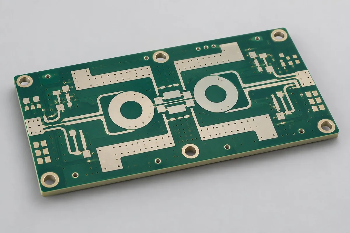
- Four-layer RO4350B specialty-dielectric RF multilayer board — Four all-specialty-dielectric layers differ from FR4 hybrid construction; pressed bonding-sheet dielectric also enters the model
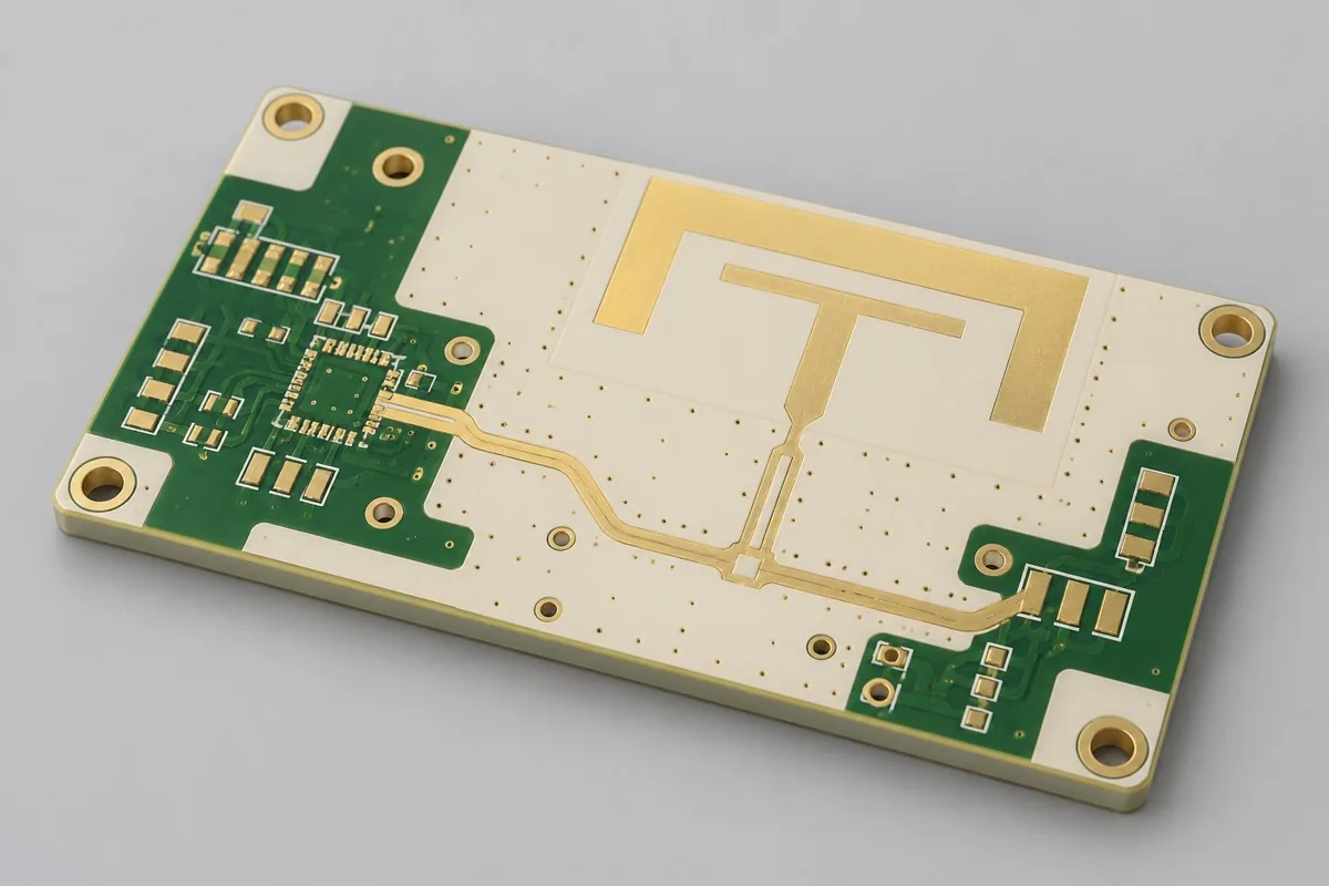
- RO3010 high-Dk miniaturized patch antenna board — High Dk reduces dimensions, but bandwidth, temperature drift, and tolerance sensitivity require separate verification
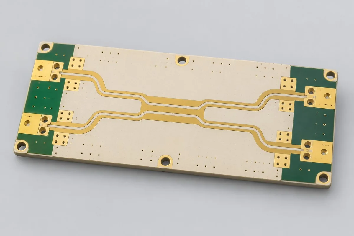
- RT/duroid 5870 double-sided microwave coupler board — 5870 low-Dk coupled lines and four-port testing; procurement value comes from coupling structure rather than a material-name change
Complete Rogers PCB product catalog · All PCB Products
High Dk resonant board material and design basis
- Engineering reference | Rogers high-frequency material comparison: Dk, Df, and test conditions: Published manufacturer material data
Record TMM10i 1.270mm/gap material revisions/design conditions; first articles focus center/passband/stopband VNA. Update drawings/checks before release after material/copper/via changes.
Request Quote for This PCB Configuration: reference product ID 330; include key circuits/interfaces, quantity, retained/changed specifications.