Engineering Selection Reference
Sub-GHz PCBs: Sub-GHz FR4 wireless board fabrication review
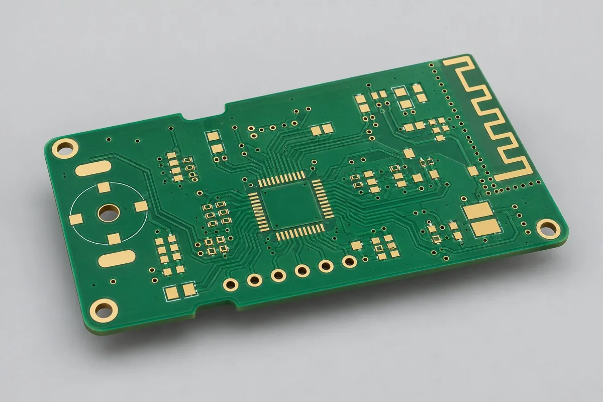
Review Sub-GHz FR4 wireless board fabrication against current drawings. Double-sided bare boards require actual bands, feedline length, antenna type, and enclosure boundaries. Compare FR4 costs for short lines without extrapolating millimeter-wave losses. Deliver material and copper keepout pattern records. Verify matching and range on assembled systems; this page is an engineering reference.
First define bare PCB prototyping or production scope for Sub-GHz PCBs. Provide Gerber data, drill files, board outline, and layer stackup, materials and processes, quantity, and fabrication acceptance requirements. FR4 serves shorter feedlines, emphasizing matching/antenna tuning rather than implying low millimeter-wave loss
Why choose this structure for Sub-GHz wireless boards?
For Sub-GHz remotes and wireless sensors with short feedlines and suitable loss budgets, start with double-sided 0.80mm FR4. This product focuses on the wireless IC-to-matching-network/antenna port structure, using a short 50Ω feedline reference target as a direct comparison option to all-specialty dielectrics.
How much do Sub-GHz RF PCBs cost, and why consider FR4?
For short feedlines within loss budgets, double-sided FR4 is a quoting alternative to specialty RF dielectrics. Costs cover the 0.80mm board, antenna copper keepouts, matching pads, through-holes, and ENIG. Wireless tuning and range testing belong to assembled systems. Compare materials at the same bands and feedline lengths before quantity, panelization, and test costs.
Quotation terms depend on the approved files, quantity, material supply, tests and delivery requirements.
Prepare a structured RFQ or use the short inquiry form.
Enter the following items in one itemized quotation: specify cost units and tax/shipping basis, with separate columns for first orders and same-revision repeat orders. The table is a procurement breakdown method, not a ready-made price list; reference specifications require approval against current fabrication drawings.
| Quotation items and pricing boundaries | Configuration inputs to confirm | Repeat orders and revision changes |
|---|---|---|
| Materials/fabrication, quoted per batch or accepted board | Shengyi S1000-2M FR4 reference grade; RF Dk from actual stackup; 2 layers; base copper 18µm/finished target 35µm | Recurs on repeat orders; material, layer-order, or copper-weight changes require requotation |
| Holes and forming, per approved hole table | Ø0.30mm ground through-holes; copper keepout at the antenna end | Repeat orders use the same fabrication revision; review processes before changing Sub-GHz antenna boundaries |
| Surface finish/packaging, noting areas and batches | ENIG pads; include antenna feedline solder mask in the model | Incurred by actual batch; confirm packaging, storage conditions, and surface-finish substitutions separately |
| Engineering/tooling preparation, identifying one-time or per-batch charges | Sub-GHz antenna boundaries: define external or onboard antennas, matching areas, and final enclosure to determine FR4 verification structures. | Verify file revisions, ownership, and storage condition before reusing old tooling; do not assume reuse is free |
| Structural/special inspections, identifying coupons, hole groups, or samples | Record antenna patterns and material lots; verify radiation metrics in the specified assembly state. Link impedance coupons to the fabrication stackup rather than reusing another material's trace widths. | List initial prototype validation and per-batch sampling separately; quote per-board requirements separately rather than assuming everything is completed once |
| Delivery scope, reports, and accepted quantity | Wireless control bare PCBs, approved material/trace widths, antenna copper keepout drawings, electrical test records, and optional port verification structures. | Retain revision links and batch records on repeat orders; list component assembly, firmware, and complete-unit testing separately |
How do Sub-GHz FR4 boards differ from Rogers high-frequency boards?
This product serves shorter wireless sensor or remote-control feedlines; specialty material boards suit paths requiring lower loss or greater consistency. Frequency, length, and actual FR4 parameters determine upgrades. Do not extrapolate low-frequency short-line prototypes to 24GHz radar. Compare under identical port and installation conditions, using actual-grade Dk.
| Comparison Dimension | Sub-GHz RF PCB fabrication | RO4350B high-frequency PCB fabrication |
|---|---|---|
| Material and Grade | Shengyi S1000-2M FR4 reference grade; RF Dk from actual stackup | Rogers RO4350B |
| Layer Count and Structure | 2 Layer | 2 Layer |
| Hole Structure and Dimensions | Ø0.30mm ground through-holes; copper keepout at the antenna end | Ø0.30mm finished through-holes; RF ground-via fence |
| Application | Sub-GHz remote-control modules; short-feedline wireless sensors | Wireless transceiver modules; RF power-amplifier driver stages |
How should Sub-GHz antenna board dimensions and copper keepouts be selected?
Start with antenna type, actual band, and enclosure space to define ground planes, matching locations, and keepouts. A 0.80mm board is a reference starting point; thickness changes affect feedline models. After enclosure or battery position changes, reverify port matching and wireless links rather than retaining antenna patterns alone.
| Decision Sequence | Required project inputs | Agreed records and deliverables |
|---|---|---|
| 1. Define application and scope | Define external or onboard antennas, matching areas, and final enclosure to determine FR4 verification structures. | Record antenna patterns and material lots; verify radiation metrics in the specified assembly state. |
| 2. Confirm structural requirements | Provide actual operating bands and line lengths to confirm the Dk model. | Link impedance coupons to the fabrication stackup rather than reusing another material's trace widths. |
| 3. Align nets with fabrication targets | Short 50Ω feedline reference target; define coupon testing separately from assembled matching-network tuning and VNA measurements | Provide target nets, layer pairs, and verification scope; review with Ø0.30mm ground through-holes and antenna-end copper keepouts |
| 4. Confirm quotation and release revision | Shengyi S1000-2M FR4 reference grade; RF Dk from actual stackup; 0.80mm reference target; ENIG pads; include antenna feedline solder mask in the model | Request quotations using material/pattern/inspection lists at the same revision; list unapproved substitutions as separate alternatives rather than including them in the baseline quotation |
Sub-GHz wireless board fabrication specifications
| Specification Items | Reference configuration or target |
|---|---|
| Material and Grade | Shengyi S1000-2M FR4 reference grade; RF Dk from actual stackup |
| Layer Count and Structure | 2 Layer |
| Total Board Thickness | 0.80mm reference target |
| Dielectric thickness and interlayer relationship | Core thickness approximately 0.73mm as a reference target |
| Base Copper and Finished Copper | Base copper 18µm/finished target 35µm |
| Hole Structure and Dimensions | Ø0.30mm ground through-holes; copper keepout at the antenna end |
| Trace Width and Spacing | 0.15/0.15mm reference design |
| Impedance Target and Measurement Methods | Short 50Ω feedline reference target; define coupon testing separately from assembled matching-network tuning and VNA measurements |
| Surface Finish | ENIG pads; include antenna feedline solder mask in the model |
| Application | Sub-GHz remote-control modules; short-feedline wireless sensors |
| Deliverables | Wireless control bare PCBs, approved material/trace widths, antenna copper keepout drawings, electrical test records, and optional port verification structures. |
Tradeoffs between FR4 lot-dependent loss and specialty dielectrics
Use actual FR4 grades and stackups for Dk/loss, not one empirical Dk across all lots. Longer feedlines or higher frequencies make specialty dielectric loss comparisons more relevant. This product is not a replacement for 24GHz radar boards.
Antenna copper keepouts, bottom ground, and matching pads: fabrication inspection
Lock antenna-end keepouts, module ground, and enclosure boundaries from circuit design. Silkscreen/panelization changes must not move matching pads. Avoid power traces interrupting two-layer ground returns, and use the same reference planes for ports and test connectors.
Actual dielectric thickness/trace width and installed matching: acceptance items
After bare board electrical testing and actual dielectric/trace-width checks, measure VNA results and operating bands with matching components installed. Antenna matching and wireless link tests are subsequent system verification. A 50Ω coupon alone cannot guarantee communication range.
Sub-GHz wireless board delivery scope
Applications: Sub-GHz remote-control modules; short-feedline wireless sensors.
Wireless control bare PCBs, approved material/trace widths, antenna copper keepout drawings, electrical test records, and optional port verification structures.
Antenna type, enclosure, and operating bands: RFQ inputs
Submit antenna type, enclosure, and operating bands to turn tabled design targets into inspectable fabrication drawings. Inputs below define pattern, material, or structural inspection scope. Freeze the quote revision with approved drawings.
| Project inputs required for review | Engineering decisions | Records/delivery as agreed in the order |
|---|---|---|
| Sub-GHz Antenna Boundary | Define external or onboard antennas, matching areas, and final enclosure to determine FR4 verification structures. | Record antenna patterns and material lots; verify radiation metrics in the specified assembly state. |
| FR4 Dielectric Model | Provide actual operating bands and line lengths to confirm the Dk model. | Link impedance coupons to the fabrication stackup rather than reusing another material's trace widths. |
Sub-GHz RF PCB fabrication: pricing, selection, and purchasing FAQ
How much do Sub-GHz RF PCBs cost, and why consider FR4?
A project-specific quotation requires review of the available files, quantity, materials, requested tests, delivery destination, taxes, shipping, and trade terms. Add specified materials, processes, and inspections not yet included to the total cost. Standard board references do not cover every configuration of this product. No current unit prices are published here; request an itemized quotation for the approved scope.Review quotation inputs and scope.
How do Sub-GHz FR4 boards differ from Rogers high-frequency boards?
This FR4 option serves shorter Sub-GHz feedlines. Specialty materials suit paths with tighter loss or consistency needs. Frequency, length, and actual grades determine upgrades. Do not extrapolate low-frequency short-line results to 24GHz. Compare under identical port and installation conditions. Review the comparison
How should Sub-GHz antenna board dimensions and copper keepouts be selected?
Define keepouts and matching locations from antenna type, band, enclosure, and ground-plane space, with board thickness in the feedline model. Battery or enclosure position changes alter installation conditions; retest matching and links. Unchanged antenna copper patterns alone do not establish unchanged performance. Review the comparison
Can Sub-GHz PCBs guarantee communication over hundreds of meters?
Range also depends on RF components, antennas, power, interference, and installation environment. Bare boards cannot provide universal range guarantees. Verify matching and operating bands first, then test links in target applications.
Can a 50Ω feedline width be reused from another FR4 board?
Check actual materials, dielectric thickness, copper weight, and solder mask; recalculate when parameters differ. The minimum 0.15mm routing value is not a fixed 50Ω width. Maintain consistent references for connectors and matching pads too.
Should low-cost wireless board quotes include antennas?
Distinguish bare boards, onboard antenna patterns, separate antenna components, and matching adjustment. Define delivery scope and antenna type to avoid comparing PCB-only fabrication with wireless-module-inclusive pricing.
How can I judge whether a Sub-GHz FR4 board merits upgrading to Rogers?
Build loss and matching budgets under identical bands, feedline lengths, antennas, and enclosures, measuring the existing FR4 reference first. If short feedlines already meet needs, material upgrades may not bring proportional benefits. Recalculate trace widths and matching when changing materials rather than only changing purchased grades.
How do per-board and per-panel Sub-GHz RF PCB fabrication quotes convert?
Freeze onboard/external antennas, matching locations, and keepouts with panelization. Depanelization edges and battery/enclosure positions retain actual ground-plane boundaries. Quotes state finished boards per panel, purchased panels, and individual-board/panel delivery state. Divide actual panel fabrication cost by accepted boards for per-board cost. List setup, special inspection, and packaging separately; theoretical utilization does not guarantee yield.
How should one-time first-order and repeat-order costs be separated for Sub-GHz RF PCB fabrication?
First confirm Sub-GHz antenna boundaries and FR4 dielectric model files, identifying whether related engineering, tooling, or test setup is charged once. Record antenna patterns and material lots; verify radiation metrics in the specified assembly state. Verify approved files and ownership before reusing tools. Current materials, fabrication, and approved inspections still incur costs. List setup after changes separately; do not rely solely on old order totals.
Can I get a Sub-GHz RF PCB fabrication budget before antenna boundary files are complete?
Describe application, outline, quantity, and available drawings for a budget listing missing items. Formal review requires external/onboard antenna, matching area, and final enclosure definitions to determine FR4 verification structures. Corresponding delivery records antenna patterns and material lots, with radiation metrics verified in specified assembly states. Confirm fabrication/inspection pricing after freezing these conditions. Initial consultation does not require all files, but estimates do not cover undefined structures.
What needs reconfirmation if materials, drill tables, or installation conditions change on repeat Sub-GHz RF PCB fabrication orders?
Provide actual bands and line lengths to confirm Dk models. Link coupons to fabrication stackups rather than reusing other materials' trace widths. Map changes individually to old material/drill table/mechanical files and determine whether drawings, operations, or measurements must change. Product name and layer count alone do not establish identical repeat-order conditions.
What configurations still need checking if two Sub-GHz RF PCB fabrication quotes use the same material?
Compare actual FR4 stackups, bands/feedline lengths, and antenna clearances. A 50Ω coupon covers fabricated structure. Range needs components and specified-environment verification and is not included in bare board scope.
Which reports need board IDs before Sub-GHz RF PCB fabrication moves from prototypes to production?
Record antenna patterns and material lots; verify radiation metrics in specified assembly states. Link coupons to fabrication stackups rather than reusing other materials' widths. Link material lots, approved fabrication files, and results to current prototype IDs. Production uses the revision after issue closure. Old coupon or artwork reports support comparison but cannot replace current inputs. Define uncovered complete product scope separately.
How can I tell whether lower low-volume unit prices actually reduce total Sub-GHz RF PCB purchasing costs?
Measure short-feedline FR4 and Rogers alternatives with identical antennas/enclosures for matching and links, including extra substitution/tuning work. Material upgrade names do not imply lower total costs. Add setup, fabrication, agreed inspection, packaging, and shipping, then divide by accepted delivered quantity. Compare same-scope totals and per-board allocations. Use current RFQ amounts and rates without assuming fixed reductions.
Sub-GHz wireless boards compared with related board types
Current configuration difference: FR4 serves shorter feedlines, emphasizing matching/antenna tuning rather than implying low millimeter-wave loss
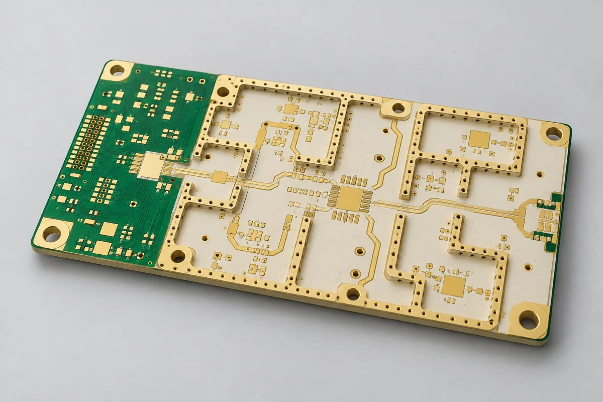
- Four-layer shielded RO4350B RF front-end board — Shield-frame pads/ground via fences are core structures; remeasure ports after shielding
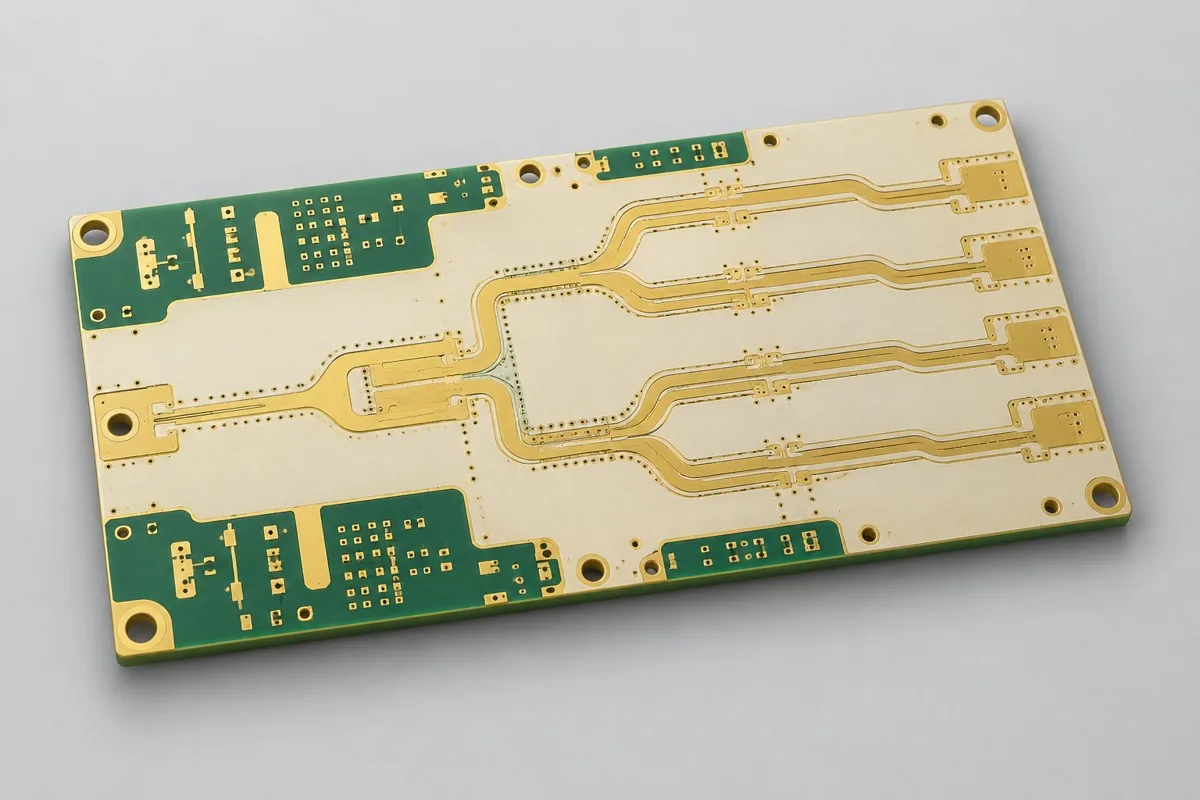
- Six-layer RO4350B multiway power-divider feed board — Six layers handle multiway feed crossings and isolation; acceptance emphasizes interpath amplitude/phase rather than single-line impedance alone
RF PCB Complete Product Catalog · All PCB Products
Sub-GHz wireless board materials and design basis
- Engineering reference | Shengyi S1000-2M: grade, supply bases, and material documentation: grade-documentation entry point; unverified performance is not cited
- Engineering reference | General high-speed interface layout: return paths, length, and layer transitions: Design methodology
When citing these references, record material revisions and design conditions for double-sided FR4 and short 50Ω feedlines. First articles focus on actual dielectric thickness/trace width and installed matching. Update drawings and inspection items before release after material, copper weight, or hole structure changes.
Request Quote for This PCB Configuration: reference product ID 234, include critical circuits/interfaces and quantity, and list specifications to retain or adjust.