
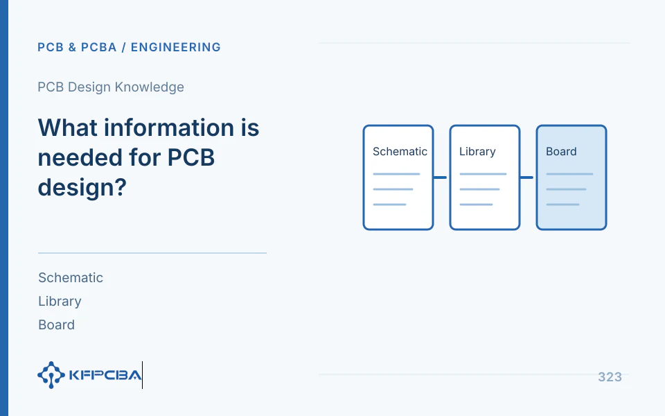
PCB design information: starting points for layout and product development commissions
Layout normally starts from approved schematics and mechanical boundaries; complete-product development also needs functions, power/interfaces, software, and validation requirements. Define responsibility for schematics, libraries, placement/routing, software, prototypes, and testing before quotation.
| Input item | PCB Layout Commission | Solution Commission |
|---|---|---|
| Functional Requirements | Describe key network and performance constraints | Define use scenarios, interfaces, specifications, fault conditions |
| Electrical Data | Schematics, netlists, BOM, component documentation | Power architecture, interfaces, and selection responsibility |
| Mechanical Data | Board outline, connectors, hole positions, and keep-out areas | Structural space, heat dissipation, and assembly relationship |
| Acceptance | Fabrication files, source files, DRC, constraint review | Staged design, prototypes, software, functional validation |
Example: how mechanical changes affect scope
Connector relocation can affect critical-net lengths, assembly direction, and tooling as well as outlines. Issue mechanical changes first, then assess routing/fabrication/test impacts. Do not send old assembly drawings with new Gerber files.
List the source and release deliverables
List filenames, revisions, purposes, owners, and approval dates. Specify source/library scope, model providers, open issues, and exceptions. Prototype records need cases, conditions, limits, and results; software DRC passes do not establish product validation.
Next Step:Design project inquiry · Pilot-production handoff support · Design and manufacturing collaboration · PCB design knowledge
First identify the documentation stage where the commission begins
The following is the author's project-responsibility method. Layout from controlled schematics, development from functional ideas, and revision of old prototypes have different starting points; legacy work also needs file-completeness and fault checks. Do not use one PCB-design total for undefined source recovery, architecture, selection, firmware, and validation. Initially state use, available files, and target deliverables; close gaps during formal review.
| Existing Data | Priority Supplement | Scope requiring confirmation |
|---|---|---|
| Functional Concept Only | Interfaces, loads, environmental conditions, and abnormal states | Architecture, circuit, program, and prototype |
| Existing Schematics | Library, mechanical, stack-up, and key constraints | Schematic Review for Inclusion |
| Existing editable PCB | Software version, library dependency, and issues | Modifications, re-routing, manufacturing package, and regression |
| Only legacy board or image | License, object, and recoverable target | Recovery Design and Re-Verification |
Convert usage requirements into acceptance questions
Requirements need more than “stable operation.” Define power/load ranges, interface counts/protocols, sampling/control tasks, startup/power-loss states, and space/temperature/maintenance constraints. Map each to validation methods, equipment providers, and criteria. Manufacturer typical circuits support starting points, not complete-unit validation with real connections and faults.
Method example: two control outputs still need load types, concurrency, protection, recovery, and power-loss states. Deliveries may include circuits/fabrication packages or prototype integration. If customers provide loads/software, state responsibilities and availability milestones. Clarify undefined functions first rather than assuming suppliers promise all undeveloped work.
Phase delivery and acceptance sheet
| phase | Delivery Recipient | Conditions to Enter Next Phase |
|---|---|---|
| Requirements and Solutions | Function, interface, boundary, and risk | Task and Supporting Responsibility Approval |
| Circuitry and Components | Schematic, BOM, and key basis | Unclosed items must be clear and critical selection confirmed |
| Layout and Routing | Library, PCB, constraints, and rule results | Mechanical, electrical, and manufacturing review |
| Manufacturing Release | Graphics, holes, stackup, coordinates, and assembly | File consistency, issue closure, revision freeze |
| Prototype Verification | Test cases, conditions, actual results, and exceptions | Achieve goals or approve limited deviations |
| Handover to Maintenance | Source files, dependencies, records, and changes | Delivery checklist and maintenance boundary confirmation |
Ucamco's public Job description supports materials, thickness, and finish as package information; Würth's digital-stackup explanation distinguishes early databases from specific materials. Separate preliminary assumptions from approved structures. TI's package directory identifies package-specific application data; approved schematics do not establish verified production footprints.
How to control costs and verify mechanical changes
Engineering example: a connector must move to the opposite side after placement. Check outline, holes, mating direction, and keepouts, then critical lengths, references, power paths, heights, and test access. Rerouting/enclosure changes exceed graphic movement. Record reasons, impacts, costs, and milestones in approved changes, updating schematics, PCB, assembly drawings, and fabrication packages together.
Retain old revisions/differences and keep separate fabrication packages out of one archive. For built prototypes, identify retests and remaining valid conclusions. Each stage can list open issues and suspended scope, but pending confirmation is not accepted completion. Compare quotations by staged outputs and revision boundaries.
Source handover must support opening in another environment
Define delivered EDA versions, library/model dependencies, fonts/plugins, export scripts, and program files; handle licenses/confidentiality as agreed. Gerber supports fabrication but may not support maintainable revisions; sources without libraries may be unreproducible. Agree on opening/re-exporting in specified tools and checking file lists/revisions rather than merely receiving archives.
DRC checks defined rules only; missing constraints are not checked automatically. Power, heat, software, and system performance still need applicable analysis/prototypes. Handover records should combine targets, actual validation, exclusions, approved exceptions, and next steps so manufacturing/maintenance know conclusion boundaries.
Source material and applicable scope
- Ucamco, Gerber Job; the public version page does not specify a revision number; checked 2026-10-17; sections: manufacturing documentation and partial implementation notes. Supports manufacturing information such as board thickness, materials, and finishes, and format-support boundaries; does not replace supplier input agreements.
- Würth Elektronik, Digital PCB Standards; public page does not specify a version; checked 2026-10-17; sections: Digital standard stackups, Material database. Supports typical database values and early-planning boundaries; does not guarantee specific grades.
- Texas Instruments, SMT & packaging application notes; directory page does not state a version; checked 2026-10-17; sections: QFN, BGA, Leaded packages, General packaging information. Supports routing to package and thermal-process documentation.
Do PCB design costs include schematics, firmware, and prototypes?
PCB layout routes existing circuits/constraints; development from functional requirements also needs architecture, selection, circuits, and software. List schematic, firmware, prototype, and test inclusion individually rather than inferring full development from the PCB-design name.
Compare costs and verification under the same conditions
Separate current files and target deliverables first. With schematics only, compare libraries, mechanics, and routing; prototype revisions need faults/changes; new development compares functions and validation tasks.
View services and configurations related to this question or Request a project quotation. For initial discussions, describe the intended use, available documentation, and expected quantity.
Related procurement and acceptance Q&A
Do PCB design costs include schematics, firmware, and prototypes?
Read: Do PCB design costs include schematics, firmware, and prototypes?
Are mechanical files still needed for layout from existing schematics?
Provide outlines, holes, connectors, keepouts, and critical constraints. Existing circuits do not automatically define mechanics, cooling, or assembly.
Read: PCB design information: starting points for layout and product development commissions
Is connector relocation only an outline change?
It may affect lengths, assembly orientation, and tooling. Issue mechanical changes first, assess routing/manufacturing/testing, then freeze consistent revisions.
Read: Example: how mechanical changes affect scope
Do design costs include source files and component libraries?
List filenames, purposes, and revisions and define source/library/model delivery responsibilities. Fabrication-only packages differ from maintainable sources.
Can passing DRC establish development acceptance?
DRC checks design rules, not product validation. Prototype acceptance separately needs cases, conditions, limits, and results; hand over open issues/exceptions with revisions.
Turn a vague requirement into a reviewable handoff
“Low power and reliable wireless operation” is not an acceptance requirement. The brief should state the supply range, operating modes, target current or battery-life condition, radio environment, antenna or enclosure constraints and the measurement method. If those values are undecided, commission a feasibility stage with a decision report rather than treating the final product design as fully specified.
| Input | Owner's decision | Review evidence |
|---|---|---|
| Mechanical envelope and connector locations | Approved drawing and tolerance revision | Placement and interface review against that revision |
| Power and interface behavior | Modes, limits and fault response | Test cases under named supply and load conditions |
| Design-source handoff | Editable files, libraries and tool versions | A second environment can open and build the release package |
Agree who resolves a conflict between the mechanical envelope and the circuit design, and how the change affects schedule and verification. This avoids accepting a PCB layout merely because the board passes a design-rule check.
Design handoff: state the next acceptance milestone
Share the functional brief, mechanics, existing schematics, firmware boundary and the next deliverable to approve. Review the design scope and submit a project inquiry with unknown requirements clearly marked.
