Engineering Selection Reference
Four-layer PCB prototyping: FR4 functional-sample fabrication review
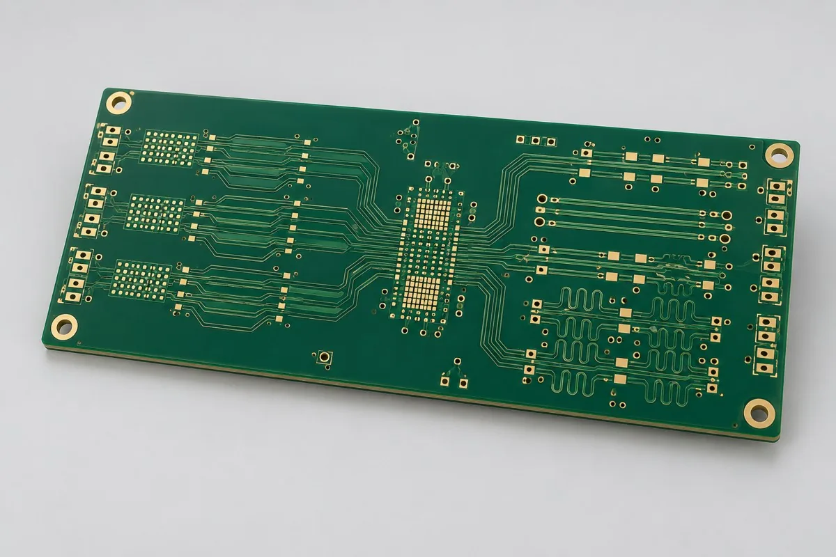
Four-layer FR4 functional-sample fabrication requires current-drawing review. Four-layer FR4 functional bare-board prototyping requires Gerber, drill files, outline, and revision, identifying this round's mechanical or manufacturing verification objective. Low-speed traces do not all need impedance coupons. Deliver electrical tests and material records; subsequent assembly debugging is separate. Approve changes and material revisions before production.
For four-layer prototyping, first define bare-board prototype or production scope. Provide Gerber, drill files, stackup, materials/processes, quantity, and fabrication acceptance requirements. Four-layer through-hole boards verify functions/assembly; Gerber comparisons and sample revisions support production transition
Why choose this structure for four-layer functional prototype
When functional-verification components mainly comprise MCUs, ordinary interfaces, and power supplies, four-layer through-hole samples establish an assemblable/electrically testable revision. This product starts with a specified grade,layer stackup, 0.30mm holes, and ENIG, focusing on an approved revision for subsequent small-batch production.
How much does four-layer prototyping cost, and what do sample charges include?
Costs include documentation/CAM setup, FR4 and layer sequence, drilling/plating, ENIG, profiling, and bare-board electrical testing. Small quantities spread fixed setup over fewer boards; production unit prices cannot simply be multiplied by sample count. Impedance coupons, blind vias, filling, and functional assembly need separate scope; specify current revision and accepted bare-board delivery quantity.
Quotation terms depend on the approved files, quantity, material supply, tests and delivery requirements.
Prepare a structured RFQ or use the short inquiry form.
Enter the following items in one itemized quotation: specify cost units and tax/shipping basis, with separate columns for first orders and same-revision repeat orders. The table is a procurement breakdown method, not a ready-made price list; reference specifications require approval against current fabrication drawings.
| Quotation items and pricing boundaries | Configuration inputs to confirm | Repeat orders and revision changes |
|---|---|---|
| Materials/fabrication, quoted per batch or accepted board | Shengyi S1000-2M FR4 reference grade, sample material lots retained; 4 layers; inner 35µm; outer base 18µm/finished target 35µm | Recurs on repeat orders; material, layer-order, or copper-weight changes require requotation |
| Holes and forming, per approved hole table | Ø0.30mm through holes; filling or blind vias not included by default | Reorders follow the same revision; review operations before sample verification-objective changes |
| Surface finish/packaging, noting areas and batches | ENIG; freeze solder-mask and legend revisions on both sides together | Incurred by actual batch; confirm packaging, storage conditions, and surface-finish substitutions separately |
| Engineering/tooling preparation, identifying one-time or per-batch charges | Sample verification purpose: specify functional, mechanical-fit, or process verification to determine segmented power, debug holes, and coupons. | Verify file revisions, ownership, and storage condition before reusing old tooling; do not assume reuse is free |
| Structural/special inspections, identifying coupons, hole groups, or samples | Deliver first-revision issue lists and change recommendations; verification samples are not automatically frozen production revisions. Link labels and reports to each revision; one report cannot cover different artwork. | List initial prototype validation and per-batch sampling separately; quote per-board requirements separately rather than assuming everything is completed once |
| Delivery scope, reports, and accepted quantity | Four-layer bare PCB samples, Gerber preview/revision approval, material/hole-dimension records, and bare-board electrical tests; archive changes/production-frozen revisions as needed. | Retain revision links and batch records on repeat orders; list component assembly, firmware, and complete-unit testing separately |
How should four-layer and six-layer controlled-impedance prototypes be selected?
MCU and ordinary-interface functional checks can start with four-layer through holes; when high-speed links or actual stackup verification are primary, six-layer impedance samples provide coupons and more layer resources. More layers do not inherently make better samples; define component-function versus transmission-structure verification before selecting tests.
| Comparison Dimension | Four-Layer PCB Prototype | Six-layer impedance PCB prototyping |
|---|---|---|
| Material and Grade | Shengyi S1000-2M FR4 reference grade, sample material lots retained | Isola 370HR FR4 reference candidate; measured stackup parameters fed back |
| Layer Count and Structure | 4 Layer | 6 Layer |
| Hole Structure and Dimensions | Ø0.30mm through holes; filling or blind vias not included by default | Ø0.25mm through holes; return vias beside critical layer transitions |
| Application | MCU functional prototypes; small-batch control-board verification | High-speed interface prototype; acquisition link prototype |
How are four-layer sample dimensions and panelization determined?
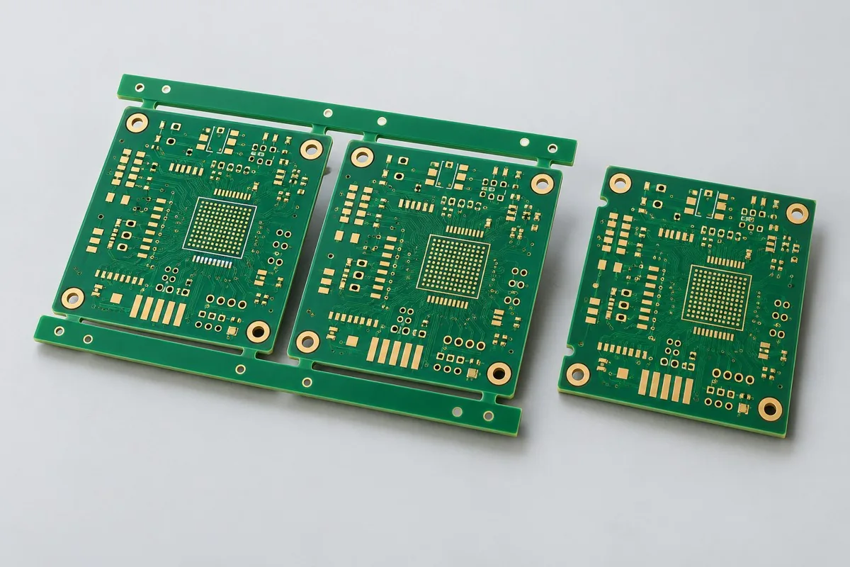
The enclosure and connectors define the individual board's mechanical boundaries; panelization accounts for placement alignment, test points, and depaneling stress. Reserve debugging and modification space without moving critical interfaces to improve panel utilization. Check copper, drills, outline, and layer sequence together in the Gerber preview, and record first-sample CAM adjustments for production transition.
| Decision Sequence | Required project inputs | Agreed records and deliverables |
|---|---|---|
| 1. Define application and scope | Specify functional, mechanical-fit, or process verification to determine whether segmented power, debug holes, and coupons are needed. | Deliver first-revision issue lists and revision recommendations; verification samples are not automatically frozen production revisions. |
| 2. Confirm structural requirements | For simultaneous variants, provide each revision's file checksum and quantity. | Link labels and reports to each revision; one report must not cover different artwork. |
| 3. Align nets with fabrication targets | Low-speed functional boards do not default to controlled impedance; list specified nets separately when needed | Provide target nets, layer pairs, and verification scope; review together with Ø0.30mm through holes; filling or blind vias are not included by default |
| 4. Confirm quotation and release revision | Shengyi S1000-2M FR4 reference grade, with sample material lots archived; 1.60mm reference target; ENIG; freeze solder-mask and legend revisions on both sides together | Request quotations using material/pattern/inspection lists at the same revision; list unapproved substitutions as separate alternatives rather than including them in the baseline quotation |
Four-layer prototype manufacturing specifications
| Specification Items | Reference configuration or target |
|---|---|
| Material and Grade | Shengyi S1000-2M FR4 reference grade, sample material lots retained |
| Layer Count and Structure | 4 Layer |
| Total Board Thickness | 1.60mm reference target |
| Dielectric thickness and interlayer relationship | Target outer-signal-to-ground spacing 0.18mm; balance inner ground/power layers |
| Base Copper and Finished Copper | Inner 35µm; outer base 18µm/finished target 35µm |
| Hole Structure and Dimensions | Ø0.30mm through holes; filling or blind vias not included by default |
| Trace Width and Spacing | 0.15/0.15mm reference design |
| Impedance target and measurement method | Low-speed functional boards do not default to controlled impedance; list specified nets separately when needed |
| Surface Finish | ENIG; freeze solder-mask and legend revisions on both sides together |
| Application | MCU functional prototypes; small-batch control-board verification |
| Deliverables | Four-layer bare PCB samples, Gerber preview/revision approval, material/hole-dimension records, and bare-board electrical tests; archive changes/production-frozen revisions as needed. |
Choosing between functional and impedance samples for low-speed designs
Functional samples do not need impedance coupons for every net, but fast-edge or special interfaces must be defined separately. Using inexpensive sample materials and then freely changing production materials/finishes introduces variables. If interface performance is the main concern, select six-layer impedance-verification samples.
Gerber previews, debug points, and panelization: manufacturing checks
Outputs include copper, solder mask, legend, drills, outline, and layer sequence; use Gerber attributes and previews to verify manufacturing intent. Coordinate test points and panel alignment with assembly plans; sample modifications need revision numbers and identified change locations.
Bare-board electrical tests, hole diameters, and production-transition records: acceptance items
After bare-board electrical, dimensional, and hole-diameter checks, samples support actual assembly and functional verification. First-article records capture material lots, stackup, and CAM adjustments so subsequent production can reference the approved revision. First-pass prototyping success is not a guaranteed outcome.
Four-layer prototype delivery scope
Applications: MCU functional prototypes; small-batch control-board verification.
Four-layer bare PCB samples, Gerber preview/revision approval, material/hole-dimension records, and bare-board electrical tests; archive changes/production-frozen revisions as needed.
Current verification objectives and parallel revisions: quotation inputs
Submit current verification objectives and parallel revisions to convert tabled design targets into inspectable fabrication drawings. The following inputs determine artwork, material, or structural inspection scope; the quotation revision freezes with approved drawings.
| Project inputs required for review | Engineering decisions | Records/delivery as agreed in the order |
|---|---|---|
| Prototype Verification Purpose | Specify functional, mechanical-fit, or process verification to determine whether segmented power, debug holes, and coupons are needed. | Deliver first-revision issue lists and revision recommendations; verification samples are not automatically frozen production revisions. |
| Parallel prototype revisions | For simultaneous variants, provide each revision's file checksum and quantity. | Link labels and reports to each revision; one report must not cover different artwork. |
Four-layer PCB prototyping: pricing, selection, and procurement FAQs
How much does four-layer prototyping cost, and what do sample charges include?
A project-specific quotation requires review of the available files, quantity, materials, requested tests, delivery destination, taxes, shipping, and trade terms. Add specified materials, processes, and inspections not yet included to the total cost. Standard board references do not cover every configuration of this product. No current unit prices are published here; request an itemized quotation for the approved scope.Review quotation inputs and scope.
How should four-layer and six-layer controlled-impedance prototypes be selected?
This four-layer through-hole configuration prioritizes MCU and ordinary-interface functional verification; six-layer impedance samples also verify stackup, coupons, and transmission geometry. High-speed interface issues require corresponding coupons; low-speed logic does not require impedance testing on every net. Review the comparison
How are four-layer sample dimensions and panelization determined?
The enclosure/connectors define individual-board mechanical boundaries; placement alignment, test points, and depaneling stress determine panelization. Improved utilization must not move critical interfaces. Check copper, holes, outline, and layer sequence together in Gerber previews, and retain CAM changes for production transition. Review the comparison
Can four-layer prototypes use inexpensive materials before changing them for production?
Substitutions may change dielectric properties, thermal processing, and solderability; sample verification does not automatically cover new materials. To compare two materials, record their parameters and results separately, and use the final approved structure for production.
Does a four-layer board not require impedance control?
Low-speed functional boards do not default to full-board impedance control, but fast-edge or specific interfaces still require net definitions per component requirements. Add targets, layer pairs, and coupons only for these nets; the four-layer designation alone cannot determine requirements.
Does a PCB prototyping quotation include soldering and debugging?
This configuration covers bare PCB samples; components, placement, programming, and functional debugging are separate. Specify whether bare boards or powered prototypes are required, then separate fabrication, materials, assembly, and debugging costs.
Can reports for two four-layer sample variants be combined to save costs?
Shared material-lot records can be discussed, but artwork, netlists, and inspection results must link separately to each revision's file checksum, quantity, and sample number. If one revision changes power segmentation and another changes debug holes, verify each task separately; one functional result must not cover different artwork.
How are per-board and per-panel four-layer prototyping quotations converted?
Provide file checksums and quantities for each variant before deciding whether to combine them on a panel. Do not merge revision-specific netlists/labels or power segmentation to save setup costs. State deliverable finished boards per panel, actual panels purchased, and individual-board/panel delivery format. Calculate fabrication cost per board by dividing actual panel fabrication charges by corresponding accepted finished boards. List setup, special inspections, and packaging separately; theoretical utilization does not guarantee yield.
How are first-order one-time costs separated from four-layer prototyping reorder costs?
First confirm sample verification objectives and parallel-revision documentation, stating whether engineering, tooling, or test setup is charged once. Deliver first-revision issue lists and revision recommendations; verification samples are not automatically frozen production revisions. Confirm files and ownership before reusing tools. Current-lot materials, fabrication, and approved inspections still incur costs; separately list setup repeated after changes instead of reusing the old order total.
Can I obtain a four-layer prototyping budget before sample-verification documentation is complete?
Provide the application, board outline, quantity, and available drawings for a budget identifying missing inputs. Formal review requires the following: specify functional, mechanical-fit, or process verification to determine segmented power, debug holes, and coupons. Corresponding delivery includes first-revision issue lists and revision recommendations; verification samples are not automatically frozen production revisions. Confirm fabrication/inspection pricing after these conditions freeze. Initial inquiries need not include every file, but estimates do not cover undefined structures.
What requires reconfirmation when four-layer prototype reorders change materials, hole tables, or mounting conditions?
For simultaneous variants, provide each revision's file checksum and quantity. Link labels and reports to each revision; one report must not cover different artwork. Match each change against prior material/hole-table/mechanical files to determine drawing revisions, process changes, or remeasurement. The same product name and layer count do not establish identical reorder conditions.
What configurations should be compared when two four-layer prototyping quotations use the same material?
Check sample verification objectives, debug holes, and variant revisions. Filling, blind vias, and impedance control are options requiring explicit definition. Functional samples differ from frozen production revisions; a single result cannot cover modified artwork.
Which reports must link to board numbers before four-layer PCB samples enter production?
Deliver first-revision issue lists and revision recommendations; verification samples are not automatically frozen production revisions. Link labels and reports to each revision; one report must not cover different artwork. Link material lots, approved fabrication files, and inspection results to current sample numbers; production uses the revision with issues closed. Old coupon or artwork-revision reports support comparison but cannot replace current manufacturing inputs. Define separate scope for complete-system items not yet covered.
How can lower small-batch four-layer prototype unit prices be checked against total procurement costs?
Combining variants on a panel can share some setup, but revision-specific labels, netlists, and issue closure remain separate. A lower price combining two revisions' tests into one result does not provide equivalent coverage. Add setup, fabrication, agreed inspections, packaging, and shipping, then divide by accepted delivery quantity to compare equal-scope total and per-board costs. Use the current inquiry for amounts and rates; do not assume fixed reductions.
Comparison of four-layer functional prototype with adjacent board types
Current configuration distinction: four-layer through holes verify functions/assembly; Gerber comparisons and sample revisions support production transition
- Six-layer differential interface impedance verification prototype — Six-layer samples include impedance coupons and link-test structures as deliverables, unlike four-layer functional samples
PCB Sample complete product catalog · All PCB Products
Four-layer functional prototype material and design basis
- Engineering reference | Shengyi S1000-2M: grade, supply bases, and material documentation: grade-documentation entry point; unverified performance is not cited
- Engineering reference | Gerber manufacturing data: layer functions, drilling, and attributes: Manufacturing File Format
- Engineering reference | Basic PCB design rules: copper weight, spacing, and hole diameter: General manufacturing design method
When citing these sources, record material revisions and design conditions for four-layer through holes, ENIG, and file revisions. First-article checks focus on bare-board electrical tests, hole diameters, and production-transition records. Update fabrication drawings and inspections before releasing changes to materials, copper weight, or hole structures.
Request Quote for This PCB Configuration: Reference product ID 248, attach critical circuits/interfaces and quantities, and list specifications to retain or adjust.