Engineering reference design · industrial-control expansion
Industrial Ethernet mainboard design: field I/O to Ethernet control
The industrial Ethernet controller uses 24V power to connect field discrete I/O, RS485, and Ethernet for status aggregation and local control. Separate real-time loops from network/logging tasks; retain frozen control states during network loss.
Custom development reference design. The following parameters are requirement configurations and design targets; validate functions and performance through agreed prototype tests.
| Functional Partition | Design and verification scope |
|---|---|
| Industrial port / I/O | Define input levels, 4 low-side output loads, and RS485 wiring; review optional CAN termination/protection separately. |
| Magnetic Isolation and Protection | Connect Ethernet PHY, magnetics, and RJ45 according to actual guides; select fieldbus protection/isolation by ground-potential differences. |
| Main Controller and Protocol Stack | The MCU runs control loops and protocol stacks; agree on periods, concurrent connections, queue limits, and timeout behavior. |
| Ethernet Data Interfaces | Distinguish 10/100M link rates from application payload throughput; test control tasks during disconnection, congestion, and reconnection. |
| Industrial Power and Voltage Regulation | Check 24V protection, 5V/3.3V, and PHY-specific supplies; record power events during load switching. |
| Buffer/anomaly recovery | Provide separate log/upgrade-image capacity and recovery access; accept interrupted upgrades, corrupt images, and parameter retention individually. |
How much does industrial Ethernet control board design cost, and how is it quoted?
Costs depend on field I/O and software tasks, not port count alone. MCU versus Linux platforms change power, memory, drivers, and system software; long-cable protection and control recovery under network saturation need validation. Separate hardware, control firmware, protocol integration, and prototypes.
Quotation terms depend on the approved files, quantity, material supply, tests and delivery requirements.
Prepare a structured RFQ or use the short inquiry form.
| Quotation Items | What services are included | What to Check When Comparing Quotes |
|---|---|---|
| Circuit and PCB Design | Field I/O and network interfaces, power protection | Reusable portions of existing designs and circuit/mechanical changes |
| Software and Validation | Control loop and communication concurrent tuning | General control and safety interlocks cannot be mixed in code |
| Prototype Preparation | Bare PCB, BOM procurement, assembly, and agreed prototype quantity | Whether material/component revisions, prototype quantities, and test targets match |
| Subsequent Revision | Record new requirements separately from post-test corrections | How agreed changes, source files, and validation results are delivered |
Should industrial Ethernet boards use MCUs or Linux core boards?
Compare MCUs for deterministic I/O and limited protocols; compare processors/core boards for complex interfaces and applications. Startup, maintenance, storage, and testing costs differ; select from functional lists first.
Does faster Ethernet mean faster control response?
Port rates describe links; control response also depends on scheduling, queues, and I/O handling. Define control periods and maximum network loads before comparing saturation, packet-loss, and recovery performance.
Do industrial-control development quotations include safety interlocks?
General control and safety interlocks are separate. Define system requirements, failure strategies, and validation separately for safety functions; ordinary networking/I/O references cannot replace safety control systems.
Reference configuration: field I/O to Ethernet control
| Configuration Field | Reference Configurations/Selections | Basis and Status |
|---|---|---|
| Finished Product Function | Equipment monitoring, data aggregation, control logic | Design Objective |
| Operating Input | 24V DC nominal, input surge/reverse-polarity protection | Design Objective |
| Network Interface | 1-port 10/100M Ethernet requirement target | Design Objective |
| Field Interfaces | 2 RS485 ports + 1 optional CAN port | Design Objective |
| Input Output | 8 digital inputs + 4 MOSFET low-side outputs | Design Objective |
| Main Controller Candidate | STM32-class MCU with Ethernet MAC | Design Objective |
| Storage Configuration | External QSPI Flash for logs/upgrade images | Design Objective |
| Power tree | 24V → 5V → 3.3V; PHY supply partitioning by model | Design Objective |
| Stackup Candidate | 6 layers, continuous ground and separate power-distribution layers | Design Objective |
| Firmware Function | Protocol adaptation, watchdog, logs, upgrade rollback | Design Objective |
| Maintenance Interface | SWD, UART console, independent recovery button | Design Objective |
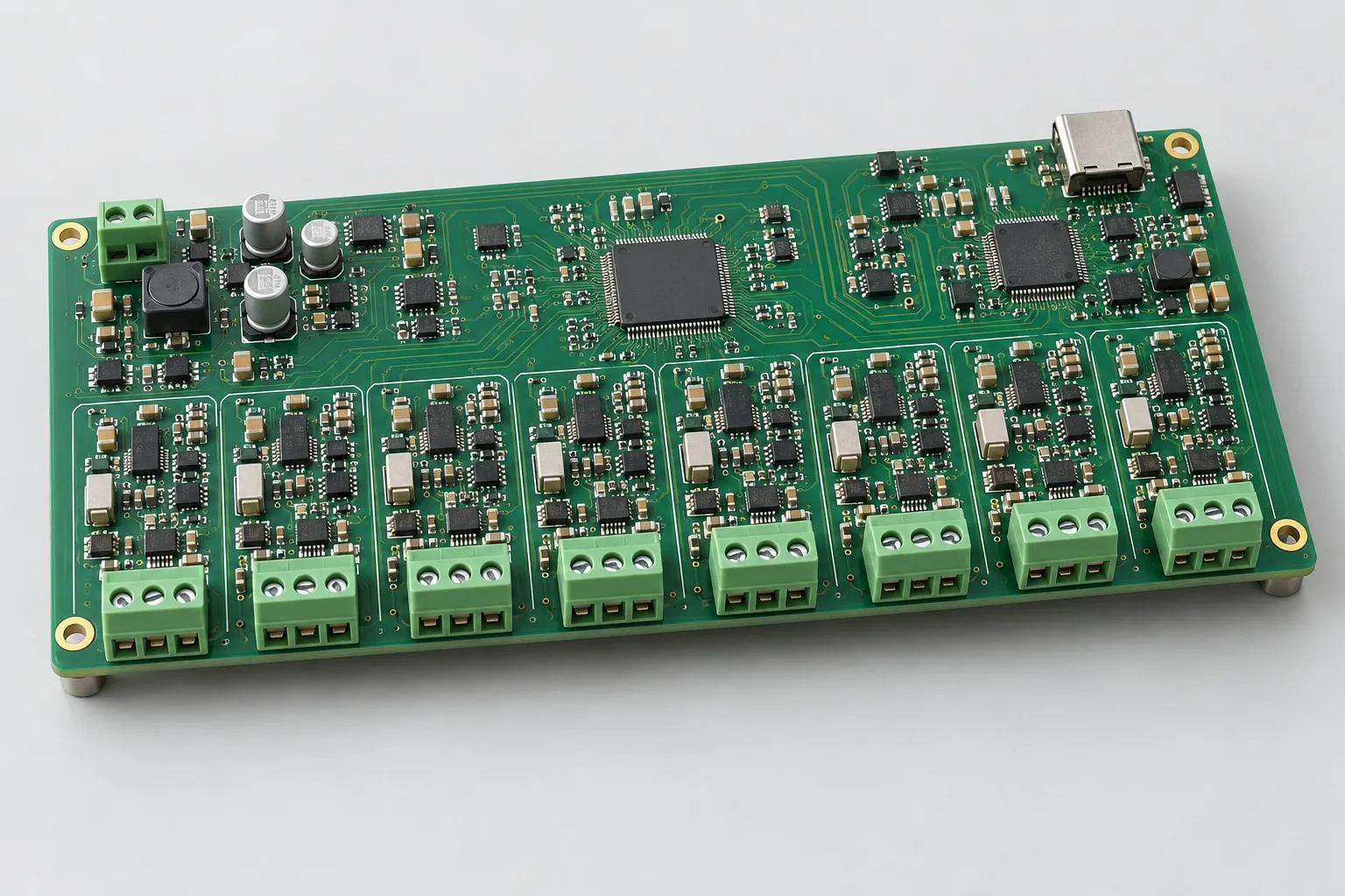
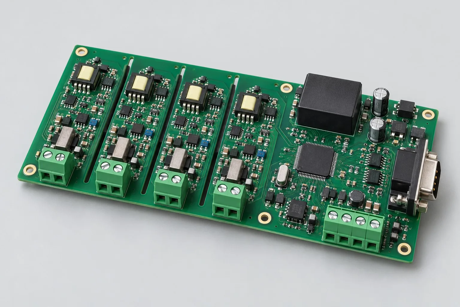
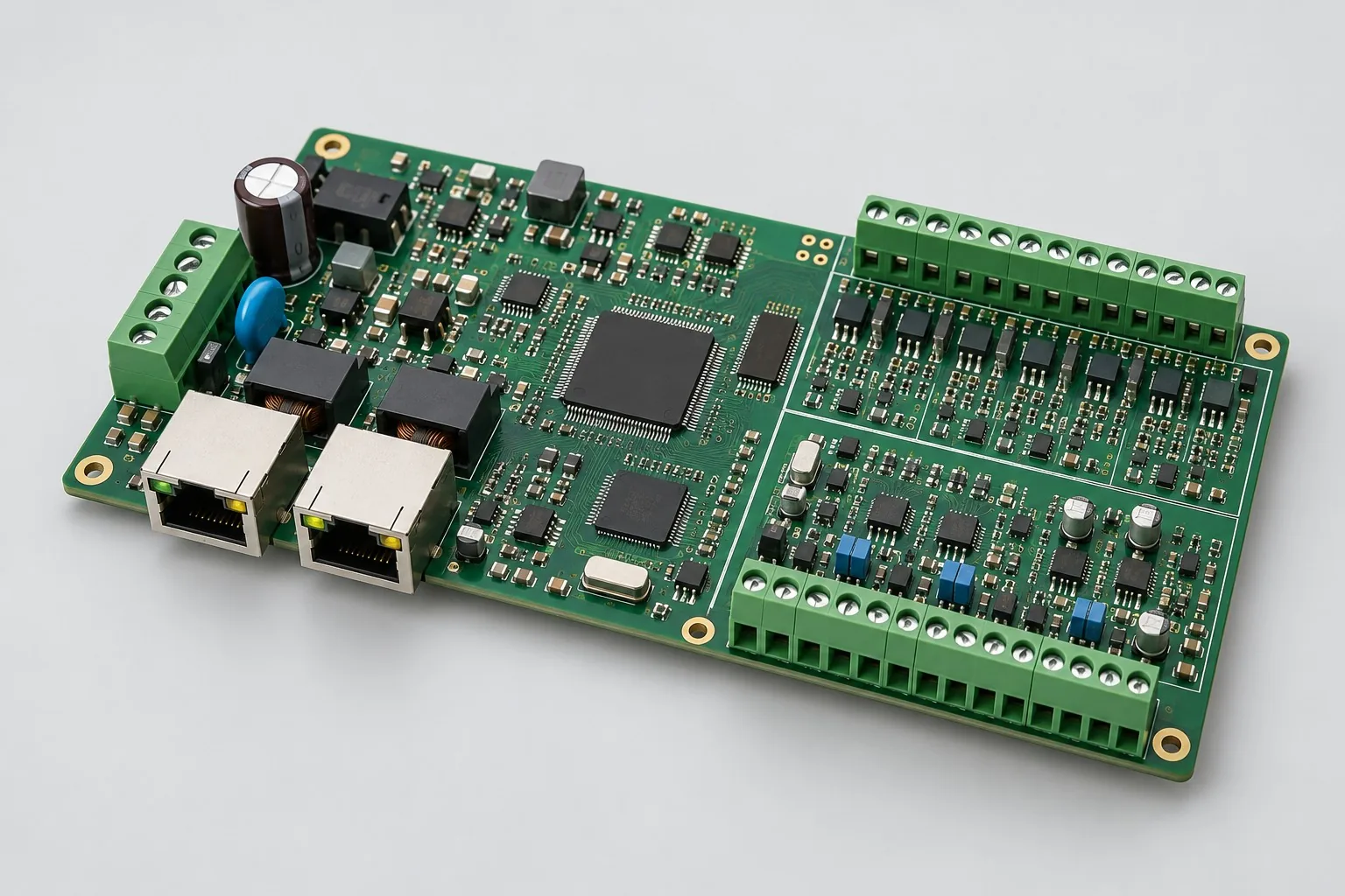
| Structural Reference | RJ45/terminals along board edges for cabinet wiring | Design Objective |
| Application boundary | Field I/O, RS485 and Ethernet aggregation for the stated control tasks | Illustrative configuration; prototype validation required |
Real-time loop and network task
MCU controllers suit deterministic acquisition and limited user interfaces; switch processor/core-board architecture when Linux applications or graphical interfaces are required.
Low-side outputs suit DC loads; select isolation/flyback components by actuators. They do not replace safety relays.
Network outages must not block field control; buffer/protocol tasks need timeout and overload behavior.
Design budget and trade-off examples
Check design targets with engineering calculations
Uploading 200-byte payloads every 20ms gives payload throughput 200/0.02=10000B/s, approximately 80kbit/s.
Conditions and Scope of Application:Add Ethernet, IP, application overhead, bidirectional traffic, and retries separately; low rates do not eliminate port isolation, ESD, or fault-recovery validation.
Replace examples with selected components and record margins; calculations support design choices, while prototype records support acceptance.
Power and layout for field I/O to Ethernet control
- Arrange PHY, magnetics, and RJ45 continuously according to connector structure; maintain complete differential-net ground references.
- Place field protection near terminals, returning disturbance currents to input ground; keep MCU crystal/reset/decoupling compact.
- Keep QSPI short and list critical nets separately; prevent I/O terminal regions from splitting reference planes.
Industrial main controller board development input
- Equipment protocol register tables, loop periods, concurrent connections
- Actuator rated/stall currents, field electromagnetic environment
- Cabinet outline, terminal positions, upgrade/recovery strategy
If circuit files exist, provide editable schematics, PCB, BOM, and current issues, and agree on review or revision scope. If only functions are defined, freeze this page's inputs before selection and circuit development. Agree separately on control-software and external-application responsibilities, interfaces, and acceptance.
Industrial main controller board phase delivery
| Stage | Engineering Work for This Proposal | Reviewable Deliverables |
|---|---|---|
| Requirements and Design Freeze | Freeze registers, control periods, network concurrency, loads, and cabinet wiring | Functional/interface requirements, mechanical revision, acceptance conditions, and open items |
| Schematic and Component Selection | Design MCU/PHY, magnetic isolation, RS485, discrete I/O, and input protection | Editable schematics, controlled BOM, footprint checks, and design calculations for these circuits |
| Layout and Routing | Constrain Ethernet/QSPI returns; separate field protection from crystal/reset domains | PCB source files, actual stackup/hole/net constraints, DRC, and assembly-dimension checks |
| Simulation/Calculation | Budget control jitter, network queues, Flash capacity, and load power | Design calculations/models, input conditions, margins, and items awaiting measurement |
| Prototype and Software | Build controller prototypes and integrate loops, protocol forwarding, logs, and upgrade rollback | Fabrication package, industrial controller prototypes, agreed firmware, register/interface tables, upgrade images, and recovery instructions |
| Testing and Version Closure | Regress control/recovery during network saturation, bus faults, and supply dips | Procedures, wiring, raw results, and decisions for the prototype revision; include issue/change and limitation lists |
Network saturation and control recovery verification
- Control-loop jitter/timeouts under full network load
- Bus shorts/disconnections, equipment miswiring, protection responses
- Interrupted upgrades, corrupt images, recovery boot
- Log integrity during supply dips and load switching
Regress control/recovery during network saturation, bus faults, and supply dips. Record equipment, conditions, revisions, and criteria in reports, identifying passed and uncovered items.
Network saturation and control-recovery validation worksheet
The table below turns field I/O to Ethernet control into executable checks. Freeze samples, equipment, environment, and permitted deviations before execution; link results to this revision's raw records.
| Verification Object | Pre-Production Freeze | How to Test Prototypes in Practice | Delivery and Acceptance Records |
|---|---|---|---|
| Real-Time and Network | Control period, maximum traffic, permitted jitter | Run discrete I/O control, RS485 polling, and log writes under full network load | Deliver control-period distributions and timeout/queue peaks against requirement limits |
| Start and Recovery | Boot sequence, firmware-recovery access, parameter-retention rules | Interrupt upgrade power, corrupt test images, and disconnect/reconnect network cables | Retain boot logs, recovery images, and parameter changes; equipment must enter agreed recoverable states |
| Field Interfaces | Isolated/shared-ground approaches, cables, miswiring conditions | Precheck disconnections/shorts and load switching with actual harnesses | Record port protection, communication recovery, and supply events; define formal standard tests separately |
Manufacturing and assembly coordination for this design
- Review substitutions for Ethernet magnetics, connectors, and protection components.
- The assembly package specifies terminal torque, wiring labels, and network-programming/configuration stations.
Link design revisions to schematics, BOM, PCB, fabrication, and software documentation. Recheck critical electrical and test conditions when fabricators adjust stackup, materials, or holes or assemblers propose substitutes.
Compare security-control board assembly and production-testing methods. This industrial Ethernet design differs from the linked security alarm board in I/O, interfaces, and tasks. The link compares related assembly scenarios, not a production model corresponding to this design. Actual production follows this project's approved BOM, assembly files, software, and test plan.
Common questions on purchasing and customization
How much does industrial Ethernet control board design cost, and how is it quoted?
A project-specific quotation requires review of the available files, quantity, materials, requested tests, delivery destination, taxes, shipping, and trade terms. Complete development separately prices circuits, firmware, prototypes, and verification. Any formula on this page organizes cost inputs; it is not a quoted rate.View cost items, calculation conditions, and sources.
How should industrial controller boards test network saturation?
Keep actual control tasks running while applying agreed traffic; record response, queues, packet loss, and resets rather than unloaded connectivity alone.
Does changing industrial Ethernet protocols require PCB rerouting?
Check controller, memory, and interface capacity first; software-only changes still need timing/load regression. Revise hardware if capacity is insufficient.
Which endpoints should divide industrial Ethernet controller budgets?
List endpoints/tasks for reference 1-port 10/100M, 2-port RS485, optional CAN, and 8 inputs/4 outputs. Hardware covers input protection, PHY, and field I/O; software covers protocols, logs, and rollback. Quote network-saturated/concurrent-load prototypes separately rather than estimating all development from one port.
What must customers provide for Ethernet controller layout-only work?
Provide approved MCU/PHY circuits, power trees, field interfaces, terminal mechanics, isolation, and load specifications. Layout implements six-layer references and net constraints. Assign protocol adaptation, control loops, rollback, and safety definitions separately; routing does not establish their completion.
Which firmware costs remain with an existing network stack?
I/O mapping, dual-RS485 scheduling, logs, watchdogs, and upgrade-image management remain. State stack providers and permitted changes; accept control response/recovery under saturation. Stack connectivity does not establish concurrent control tasks are resolved.
How should industrial controller source files cover recovery and maintenance?
Agree on exact PHY/memory revisions, network/field pinouts, recovery-button circuits, and SWD/UART access. Software includes log formats, image checksums, rollback, and tool configurations. Retain traffic/I/O states in tests so field teams distinguish network loss, software faults, and supply resets.
Is adding CAN a minor software change?
Check reserved controller, transceiver, protection, terminals, and power first. New physical ports require circuit/layout changes and message, queue, and bus-error recovery definitions. Existing CAN hardware still needs concurrency regression with Ethernet, RS485, and I/O; added message count alone cannot estimate effort.
What must customers provide for sensors on industrial controllers with 8 inputs and 4 outputs?
For inputs, provide electrical types, normal/fault levels, and cable lengths; for outputs, startup current, flyback, and communication-loss states. Define mapping/concurrency cases for the 8-input/4-output reference; terminal shape does not establish compatibility. Customer sensors/loads are test equipment, with prototype quantity, loans, and returns agreed in the commission.
How should I prepare an RFQ before commissioning industrial Ethernet control board design?
Initially describe target functions, application, and existing files. Engineering quotations further confirm register tables, loop periods, and concurrent connections; actuator rated/stall currents and electromagnetic environment; cabinet outlines, terminal positions, and upgrade/recovery strategies. Provide editable schematics, PCB, and BOM for existing circuits, and revisions/reproduction records for faulty prototypes. List documentation gaps as review tasks so quotations do not use different assumptions.
How should industrial Ethernet control board prototype validation costs be compared by operating condition?
Freeze prototype quantity, revision, equipment, and criteria sources first. For real-time/network operation, freeze periods, traffic, and jitter, then run discrete I/O, RS485 polling, and logs under saturation. For boot/recovery, freeze sequence, recovery access, and retention, interrupt upgrades, corrupt test images, and reconnect cables. For field interfaces, freeze isolation/shared ground, cables, and miswiring; precheck actual-harness shorts/disconnections and load switching. State whether raw data and issue closure are delivered; one power-on pass is not complete validation.
Compare related designs and plan the next step
Eight-channel simultaneous monitoring and acquisition board design · Four-channel isolated 4–20mA process acquisition board design
Return to multi-layer PCB design selection · Select solution by device function · Discuss your design requirements
Engineering reference | STM32F4 hardware startup: power, reset, boot, and debugging: AN4488 references power, clocks, reset, and hardware development for applicable STM32 devices; PHYs, industrial ports, and protocols need actual component documentation separately.