Engineering reference design · prototype validation pending
Eight-channel acquisition board design: eight signals to synchronized data
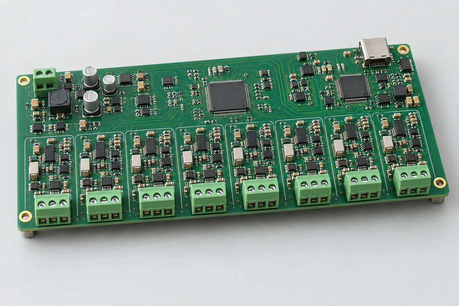
The eight-channel simultaneous acquisition board conditions eight sensor signals for a simultaneous ADC; the controller timestamps, buffers, and uploads data over wired interfaces. Freeze measurement ranges, effective bandwidth, and continuous data volume for industrial monitoring before choosing RS485 summaries or Ethernet raw data.
Custom development reference design. The following parameters are requirement configurations and design targets; validate functions and performance through agreed prototype tests.
| Functional Partition | Design and verification scope |
|---|---|
| Eight-Channel Analog Input | Define range, source impedance, and sensor excitation for each differential input; terminal voltage limits cannot simply match bare ADC ranges. |
| Anti-Aliasing and Conditioning | Design protection, RC anti-aliasing, and range conversion per channel; include matching error and crosstalk in front-end budgets. |
| Synchronize ADC and Clock | ADS131M08-class ADCs use common clocks and synchronization; freeze sample rate, filter settings, and timestamps together. |
| Buffer/data interface | SPI feeds controller buffers; budget headers, timestamps, and retransmission separately for RS485 summaries and continuous Ethernet upload. |
| Low-Noise Power Supply | Separate 24V input conversion from low-noise analog domains; check reference/supply noise and temperature-driven zero/gain drift. |
| Channel Calibration and Crosstalk | Use common-source inputs to measure interchannel amplitude/phase differences and crosstalk; retain per-channel calibration and distinguish 24-bit encoding from effective resolution. |
How much does eight-channel simultaneous acquisition board design cost, and how is it quoted?
Quote front ends, synchronization, and data software separately. Input ranges, bandwidth, and errors determine conditioning/calibration work; continuous-upload targets affect buffers/interfaces. Routing an eight-channel ADC PCB is not directly comparable to development including per-channel calibration, frames, and continuous-acquisition validation.
Quotation terms depend on the approved files, quantity, material supply, tests and delivery requirements.
Prepare a structured RFQ or use the short inquiry form.
| Quotation Items | What services are included | What to Check When Comparing Quotes |
|---|---|---|
| Circuit and PCB Design | Eight analog front ends, synchronization clock, and error budget | Reusable portions of existing designs and circuit/mechanical changes |
| Software and Validation | Data upload and per-channel calibration | Agree separately on sampling firmware, data frames, calibration-coefficient management, and host interfaces |
| Prototype Preparation | Bare PCB, BOM procurement, assembly, and agreed prototype quantity | Whether material/component revisions, prototype quantities, and test targets match |
| Subsequent Revision | Record new requirements separately from post-test corrections | How agreed changes, source files, and validation results are delivered |
How should simultaneous and polled eight-channel acquisition be selected?
Compare simultaneous sampling when phases/transients must be compared at the same instant; assess polling for slow process variables. Select by bandwidth and permitted channel skew; equal channel counts do not make acquisition boards equivalent.
Are 24-bit acquisition boards always more accurate than lower-resolution boards?
Encoding bits do not establish whole-board error. Inputs, references, resistors, noise, and calibration all matter. Compare effective performance by range/bandwidth before choosing ADC/front ends rather than purchasing by bit count.
Does eight-channel acquisition development include host software?
Agree separately on sampling firmware, data frames, calibration management, and host interfaces. Continuous recording also needs upload speed, buffering, and dropped-sample detection; a USB interface does not establish complete acquisition software.
Reference configuration: eight signals to synchronized data
| Configuration Field | Reference Configurations/Selections | Basis and Status |
|---|---|---|
| Reference application | Eight-channel simultaneous analog acquisition | Illustrative configuration; prototype validation required |
| Acquisition Channel | 8 differential input reference requirements | Design Objective |
| Data Rate | 8kSPS per channel is an example target; system results require testing | Design Objective |
| Component Candidate | ADS131M08-class 8-channel simultaneous ADC + MCU | Design Objective |
| Bit Depth | ADC uses 24-bit encoding; not equivalent to effective system accuracy | Design Objective |
| Power Supply Objective | 24V DC input; independent low-noise 3.3V analog domain | Design Objective |
| Input Conditioning | RC anti-aliasing + protection; sensor-defined measurement ranges | Design Objective |
| Communication Interface | SPI to MCU; RS485 or Ethernet upload | Design Objective |
| Stackup Candidate | 6 layers; partition analog/digital by current loops | Design Objective |
| Synchronization Function | Common sample clock, trigger input, timestamps | Design Objective |
| Firmware Output | Sampling driver, CRC checking, buffer-overflow alarms | Design Objective |
| Calibration Interface | Zero/gain coefficient storage and raw-data export | Design Objective |
Sampling bandwidth and upload path
For low-frequency process-variable monitoring, simultaneous ΔΣ ADCs simplify multichannel synchronization; for higher bandwidth, switch to high-speed ADCs rather than only increasing serial-port speed.
RS485 suits low-rate summaries; calculate raw continuous 8-channel links from resolution, protocol overhead, and buffering.
Design range conversion, sensor excitation, and isolation separately first; bare ADC ranges are not terminal voltage limits.
Design budget and trade-off examples
Check design targets with engineering calculations
Eight channels at 10kS/s each and 24bit per point produce 8×10000×24=1.92Mbit/s raw data, or 240kB/s packed into 3-byte samples.
Conditions and Scope of Application:This example uses 10kS/s for data-volume comparison, recorded separately from the 8kSPS target above. Add packet, timestamp, retransmission, and buffering overhead; sample rate is not effective signal bandwidth and requires front-end/filter validation.
Replace examples with selected components and record margins; calculations support design choices, while prototype records support acceptance.
Power and layout for eight signals to synchronized data
- Place terminals → protection → RC → ADC continuously; locate matched inputs and reference capacitors near devices.
- Control returns with complete ground references; keep digital traces out of sensitive front ends and switching nodes away from clocks/references.
- Use short analog test-point branches; constrain common clocks and synchronization-trigger nets.
Eight-channel acquisition development input
- Eight signal types, full-scale ranges, source impedances, bandwidths
- Synchronization-error targets, continuous recording duration, upload modes
- Operating temperature, isolation requirements, calibration traceability
If circuit files exist, provide editable schematics, PCB, BOM, and current issues, and agree on review or revision scope. If only functions are defined, freeze this page's inputs before selection and circuit development. Agree separately on control-software and external-application responsibilities, interfaces, and acceptance.
Eight-channel acquisition phase delivery
| Stage | Engineering Work for This Proposal | Reviewable Deliverables |
|---|---|---|
| Requirements and Design Freeze | Freeze eight signals, bandwidth, synchronization tolerance, upload modes, and isolation/calibration requirements | Functional/interface requirements, mechanical revision, acceptance conditions, and open items |
| Schematic and Component Selection | Design input protection/conditioning, ADC/reference/clock, controller buffers, and communication circuits | Editable schematics, controlled BOM, footprint checks, and design calculations for these circuits |
| Layout and Routing | Maintain continuous front-end-to-ADC signal flow and constrain clocks, reference grounds, and digital returns | PCB source files, actual stackup/hole/net constraints, DRC, and assembly-dimension checks |
| Simulation/Calculation | Budget error, noise, data rates, and buffers; choose filter/upload settings | Design calculations/models, input conditions, margins, and items awaiting measurement |
| Prototype and Software | Build acquisition prototypes and integrate ADC drivers, timestamps, CRC, calibration storage, and export | Fabrication package, eight-channel prototypes, driver/data-interface firmware, calibration tables, raw-data export, and recovery instructions |
| Testing and Version Closure | Test common-source synchronization, crosstalk, temperature drift, and receiver-pause recovery; deliver eight-channel data-integrity records | Procedures, wiring, raw results, and decisions for the prototype revision; include issue/change and limitation lists |
Eight-channel synchronous and crosstalk verification
- Common-source channel consistency, phase difference, and crosstalk
- Noise/distortion records with shorted inputs and full scale
- Zero/gain drift across supplies and temperatures
- CRC, overflow, and reconnection/retransmission statistics during extended uploads
Test common-source synchronization, crosstalk, temperature drift, and receiver-pause recovery; deliver eight-channel data-integrity records. Record equipment, conditions, revisions, and criteria in reports, identifying passed and uncovered items.
Eight-channel synchronization and crosstalk validation worksheet
The table below turns eight signals to synchronized data into executable checks. Freeze samples, equipment, environment, and permitted deviations before execution; link results to this revision's raw records.
| Verification Object | Pre-Production Freeze | How to Test Prototypes in Practice | Delivery and Acceptance Records |
|---|---|---|---|
| Channel Consistency | Sensor ranges, sample rates, synchronization error, filter settings | Distribute a common-source signal across eight channels and sweep agreed frequencies/amplitudes | Deliver per-channel gain/phase differences and calibration coefficients; list source/distribution-network errors separately |
| Crosstalk immunity | Channel routing, maximum amplitude, permitted crosstalk | Apply full-scale excitation to one channel; short others or connect equivalent impedances according to operating wiring | Retain affected-channel spectra and excitation conditions; no-input noise alone is insufficient |
| Data Integrity | Continuous sampling duration, upload protocol, buffer size, overflow strategy | Upload maximum agreed data volume, then pause and reconnect the receiver | Check sequence/CRC, timestamps, and overflow flags, explaining retransmitted and discarded records |
Manufacturing and assembly coordination for this design
- Trace low-noise component/reference supply batches; review error budgets for critical analog substitutions.
- Fixtures reserve eight synchronized inputs, clock probes, and independent calibration stations.
Link design revisions to schematics, BOM, PCB, fabrication, and software documentation. When fabricators adjust stackup, materials, or holes, or Assembly parties propose substitutions, recheck critical electrical and test conditions together.
Common questions on purchasing and customization
How much does eight-channel simultaneous acquisition board design cost, and how is it quoted?
A project-specific quotation requires review of the available files, quantity, materials, requested tests, delivery destination, taxes, shipping, and trade terms. Complete development separately prices circuits, firmware, prototypes, and verification. Any formula on this page organizes cost inputs; it is not a quoted rate.View cost items, calculation conditions, and sources.
How to accept eight-channel acquisition synchronization?
Apply comparable channel signals and record timing/phase differences, clock conditions, and acquisition settings against permitted deviations.
How to record sampling issues for acquisition boards?
Retain sequence numbers, timestamps, buffering, and upload logs; check missing data at full load. Interface communication alone does not establish continuous acquisition.
How should eight-channel acquisition projects create comparable budgets?
Quote eight front ends/error budgets, common clocks, SPI buffering/upload, and per-channel calibration separately. 8kSPS per channel is a reference target; align ranges, storage formats, and upload endpoints. PCB-only work cannot be compared directly with development including host calibration software.
What should layout review check when eight-channel schematics are complete?
Define input common mode, differential ranges, references, clocks, and SPI constraints for ADS131M08-class devices, retaining low-noise analog power and continuous returns. Review undefined protection/filtering circuits first; six-layer routing alone does not establish 24-bit system accuracy or continuous synchronized records.
Which development tasks are added when RS485 upload changes to Ethernet?
Calculate link budgets from eight-channel rates and actual framing overhead, then check processors, buffers, and network interfaces. Itemize new protocols, sequence numbers, overflow alarms, and continuous-recording integration. Even with reusable ADC front ends, connector changes alone cannot retain previous upload acceptance.
How should synchronized acquisition source data and code be specified?
Beyond schematics, PCB, and BOM, agree on common-clock configuration, filter settings, CRC, zero/gain coefficient formats, and raw-data export tools. Retain same-revision channel amplitude/phase, noise, and dropped-sample logs so customers can recalculate errors and maintain calibration rather than receiving processed curves alone.
Can acquisition ranges be changed simply by replacing resistors?
Check front-end common mode, protection clamps, anti-aliasing, and ADC differential range. Resistors also affect noise and temperature drift, requiring new budgets and per-channel calibration. Separate conditioning changes, PCB effects, software conversion, and regression; material-price differences cannot cover complete revisions.
Can reducing eight channels to four lower development costs?
Defined ADC, clock, and protocol portions may be reusable, but four-channel material savings depend on component approaches. List retained/removed channels and cases, distinguishing prototype material reductions from engineering reductions. Halving channels does not automatically halve synchronization, buffering, and calibration development.
How should I prepare an RFQ before commissioning eight-channel simultaneous acquisition board design?
Initially describe target functions, application, and existing files. Engineering quotations further confirm eight signal types, full scales, source impedances, and bandwidths; synchronization error, recording duration, and upload; temperature, isolation, and calibration traceability. Provide editable schematics, PCB, and BOM for existing circuits, and revisions/reproduction records for faulty prototypes. List documentation gaps as review tasks so quotations do not use different assumptions.
How should eight-channel simultaneous acquisition prototype validation costs be compared by operating condition?
Freeze prototype quantity, revision, equipment, and criteria sources first. For consistency, freeze ranges, rates, synchronization error, and filters, distribute common-source signals, and sweep frequencies/amplitudes. For crosstalk, freeze routing, maximum amplitude, and limits; excite one channel fully and short/terminate others per operating wiring. For data integrity, freeze duration, protocol, buffers, and overflow strategy; upload maximum data, pause receivers, and reconnect. State whether raw data and issue closure are delivered; one power-on pass is not complete validation.
Compare related designs and plan the next step
Industrial Ethernet main controller board design solution · Four-channel isolated 4–20mA process acquisition board design
Return to multi-layer PCB design selection · Select solution by device function · Discuss your design requirements
Documentation Basis and Boundaries
Engineering reference | ADS131M08 component reference: selection conditions and board-level verification: ADS131M08 documentation references ADC inputs, synchronization, filtering, and interfaces; terminal conditioning, whole-board accuracy, and link throughput need independent design/validation.