Engineering reference design · prototype validation pending
Aluminum-core LED design: light emission and IMS heat conduction
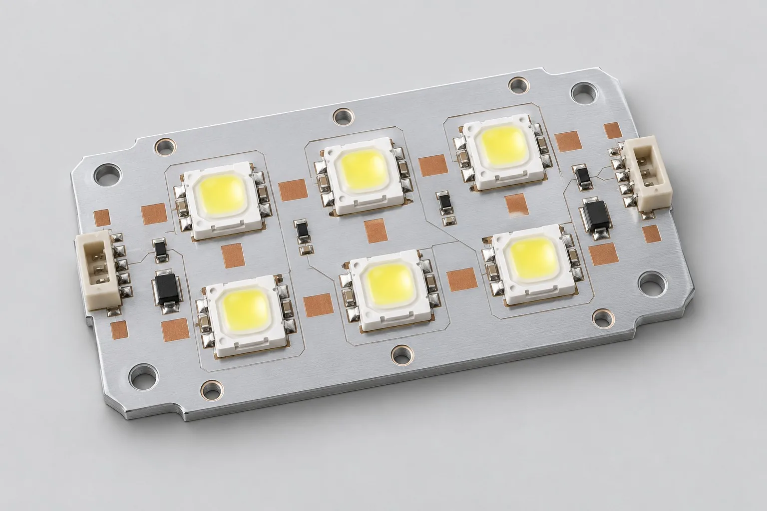
Aluminum-core LED modules place arrays on single-layer IMS, conducting heat through insulation, interfaces, and heat sinks with external constant-current drive. Six series LEDs/700mA are examples. Deliverables define optical positioning, mounting, and insulation boundaries.
Custom development reference design. The parameters below are requirement configurations and design targets; validate product performance through agreed prototype tests.
| Functional Partition | Design and verification scope |
|---|---|
| Constant Current Drive Input | Select external current drivers by string drops/current; mistake-proof inputs and confirm harness drops. |
| LED string/copper trace | Arrange series LEDs/copper by current, thermal area, and lens centers; verify thermal-pad footprints individually. |
| IMS dielectric | Select IMS insulation by conductivity, thickness, and withstand-voltage data; confirm whole-board insulation mechanically. |
| Aluminum base and heat sink interface | Core/TIM/heat-sink flatness, fastening, and screw-hole boundaries jointly determine thermal contact. |
| Current and Thermal Distribution | Estimate losses/hotspots at target current; NTC/specified points are not directly junction temperatures. |
| Installation / Temperature Rise Measurement | At fixed mounting, measure heat, light, and approved insulation; retain TIM/heat-sink revisions. |
How much does aluminum-core LED design cost, and how are quotes calculated?
Compare placement and installed thermal chains. IMS dielectrics, insulation, interfaces, and heat sinks change selection/verification. PCB layout, heat-sink mechanics, and optics are distinct. Identify actual lights/mounting samples and separate boards from development effort.
Quotation terms depend on the approved files, quantity, material supply, tests and delivery requirements.
Prepare a structured RFQ or use the short inquiry form.
| Quotation Items | What services are included | What to Check When Comparing Quotes |
|---|---|---|
| Circuit and PCB Design | LED placement, IMS dielectrics, and installed thermal chains | Reusable portions of existing designs and circuit/mechanical changes |
| Software and Validation | Optical and temperature rise testing | LED layout, thermal budgeting, and mechanical heat sinks are separately agreed tasks |
| Prototype Preparation | Bare PCB, BOM procurement, assembly, and agreed prototype quantity | Whether material/component revisions, prototype quantities, and test targets match |
| Subsequent Revision | Record new requirements separately from post-test corrections | How agreed changes, source files, and validation results are delivered |
How should aluminum-core and FR4 LED boards be selected?
Compare heat sources, insulation, and mounting paths, not material names alone. Evaluate cores with dielectrics/interfaces/heat sinks. Lower heat loads may suit FR4.
Is higher thermal conductivity always better for aluminum-core LEDs?
Material conductivity is only part of the chain; thickness, contact interfaces, and mounting affect temperature. Compare equal-heat/equal-sink rises rather than treating material values as product cooling.
Do aluminum-core LED development quotes include heat-sink design?
Layout, thermal budgets, and heat-sink mechanics are separately agreed. Provide existing mounting conditions. New sinks, optics, and complete verification are not automatic PCB fee inclusions.
LED emission and IMS heat conduction reference configuration
| Configuration Field | Reference Configurations/Selections | Basis and Status |
|---|---|---|
| Finished Product Function | LED array emission and heat conduction | Design Objective |
| Load Reference | 6 LED series connection requirement example | Design Objective |
| Drive Current Target | 700mA, subject to LED/cooling verification | Design Objective |
| Power Structure | External constant-current drive; input selected by LED drops | Design Objective |
| Substrate Candidate | Single-layer aluminum base IMS | Design Objective |
| Insulating Dielectric | Conductivity/withstand voltage/thickness per supplier data | Design Objective |
| Copper Thickness Selection | Review current/heat/etchability together; do not combine extreme values | Design Objective |
| Mechanical Structure | Screw hole fixation plus insulating thermal interface material | Design Objective |
| Temperature Monitoring | On-board NTC or enclosure temperature sensing points | Design Objective |
| Optical Interface | Lens positioning pin and LED center alignment | Design Objective |
| Connection Method | Error-proof power pad/wire harness terminal | Design Objective |
| Validation outputs | Thermal maps/resistance estimates and optical/insulation plans | Design Objective |
Dielectric interface and heat sink thermal path
Aluminum-core PCB heat conduction is only one part of the thermal path; dielectric, interface contact, and heatsink must all enter the thermal budget.
Calculate electrical input from current and forward-voltage drop; use an appropriate LED thermal model or supported optical-power data to estimate heat dissipation.
Insulation depends on materials/mechanics; metal cores are not inherently safe insulation.
Design budget and trade-off examples
Check design targets with engineering calculations
At LED/device dissipation 6W and assumed effective device-to-ambient resistance 8℃/W, rise is about 48℃. At ambient 40℃, estimated temperature is 88℃.
Conditions and Scope of Application:Resistance is assumed. Distinguish junction/joint/case temperatures. Remeasure changed interfaces/sinks/mounting; do not infer lifetime.
Replace examples with selected components and record margins; calculations support design choices, while prototype records support acceptance.
LED emission and IMS heat conduction power/layout
- Continuous thermal paths from LED pads to substrates; spacing prevents overlapping hotspots.
- Define conductive/insulating boundaries around screws and specified isolation from metal undersides.
- Freeze lens/edge tolerances first; optical changes must not shift pads arbitrarily.
Aluminum-based LED module R&D input
- LED thermal resistance, voltage drop, and allowable junction data
- Heat-sink three-dimensional model, mounting force, interfaces, and environment
- Insulation targets, lenses, and mounting-hole drawings
For existing circuits, provide editable schematics, PCB files, BOMs, and current issues, agreeing review/revision scope. For functional requirements alone, freeze this page's inputs before selection and circuit development. Define base-board ports, test wiring, and assembly scope; review added active/control circuits separately.
Aluminum-based LED module phase delivery
| Stage | Engineering Work for This Proposal | Reviewable Deliverables |
|---|---|---|
| Requirements and Design Freeze | Freeze LEDs, current, lenses, insulation, and sink/TIM mounting | Functional/interface requirements, mechanical revision, acceptance conditions, and open items |
| Schematic and Component Selection | Define strings, external drives, keyed terminals, and temperature points | Editable schematics, controlled BOM, footprint checks, and design calculations for these circuits |
| Layout and Routing | Lay out thermal pads, copper, lenses, and screw insulation | PCB source files, actual stackup/hole/net constraints, DRC, and assembly-dimension checks |
| Simulation/Calculation | Calculate device/dielectric/TIM/sink/ambient chains and mounting sensitivity | Design calculations/models, input conditions, margins, and items awaiting measurement |
| Prototype and Software | Build modules, assemble with specified torque/TIM, and connect approved drives | Manufacturing package, modules, string/lens drawings, mounting/interface specifications, wiring; no baseline control firmware |
| Testing and Version Closure | Measure specified points, junction-estimation basis, light, and insulation; compare mounting combinations | Procedures, wiring, raw results, and decisions for the prototype revision; include issue/change and limitation lists |
LED module thermal chain and optical verification
- Steady-state rise and infrared maps at target current
- Estimate junction temperature using correct test points/models
- Comparison of installation torque and interface material differences
- Luminous flux/illuminance and insulation test plan
Measure temperature points, junction-estimation basis, light, and insulation across mounting combinations. Reports identify equipment, conditions, revisions, and criteria, recording passed/uncovered items.
LED module thermal-chain/optical worksheet
The table turns LED/IMS thermal behavior into checks. Freeze samples, equipment, environment, and tolerances; link results to current raw records.
| Verification Object | Pre-Production Freeze | How to Test Prototypes in Practice | Delivery and Acceptance Records |
|---|---|---|---|
| Thermal Chain | LED thermal models, dielectrics, TIM, sinks, and torque | Fix actual current, such as reference 700mA; measure specified points/maps | Deliver dielectric/TIM/sink revisions and junction-estimation basis; surface temperature is not junction temperature |
| Mounting Sensitivity | Contact flatness, TIM thickness, and fastening range | Compare steady-state rises across approved mounting combinations | Deliver combination/temperature tables and assembly methods, beyond core conductivity alone |
| Optical and Insulation | Series LED arrangements, drivers, and product insulation requirements | Measure light at approved current; perform insulation tests to defined standards | Retain optical wiring, test basis/results; metal cores do not automatically meet product insulation |
Manufacturing and assembly coordination for this design
- Fabricators confirm dielectric grades/metal thickness; review finishes and soldering temperatures together.
- Screws, burrs, and TIM thickness affect insulation/heat; define in assembly drawings.
Link design revisions to schematics, BOM, PCB, fabrication, and software documentation. When fabricators adjust stackup, materials, or holes, or Assembly parties propose substitutions, recheck critical electrical and test conditions together.
Common questions on purchasing and customization
How much does aluminum-core LED design cost, and how are quotes calculated?
A project-specific quotation requires review of the available files, quantity, materials, requested tests, delivery destination, taxes, shipping, and trade terms. Complete development separately prices circuits, firmware, prototypes, and verification. Any formula on this page organizes cost inputs; it is not a quoted rate.View cost items, calculation conditions, and sources.
What should aluminum-core LED assembly files include?
List positions, insulation, fastening, interfaces, and sink installation so thermal tests match actual assemblies.
Can ambient temperature directly estimate junction temperature?
Heat, paths, and interfaces are also needed. Establish budgets and verify actual mounting temperatures; ambient is not junction temperature.
How should aluminum-core LED budgets separate boards and mounting systems?
For six series LEDs at 700mA, list placement/IMS/external drive, then sinks/interfaces/optical mounting. Measure board rises and full optics separately. Existing sinks reduce mechanical work, not installed thermal-chain verification.
Which thermal constraints are needed for layout-only aluminum-core LEDs?
Provide LED packages/drops, external drives, screws, lens centers, dielectrics, and interfaces. Layout covers placement/manufacturing files. Without sinks/mounting, material names cannot guarantee continuous 700mA; budget heat first.
Do aluminum-core LED boards need dimming firmware?
This reference is a light/thermal structure with external constant-current drive; baseline boards need no MCU. Added NTC/dimming/derating requires defined sensing/control locations and separate firmware endpoints. Layout alone is not a complete dimming system.
How should LED sources support component changes?
Retain footprints/centers, series wiring, dielectrics, screws, insulation, drive ranges, and optical positioning. Tests identify lots/current/cooling/temperature maps so changes reassess voltage/heat, not just reuse pads.
How are fees assessed when six LEDs become more?
Calculate new drops/headroom, then outline/lenses/copper/heat. List reusable mounting separately from placement and thermal/optical regression. More LEDs add more than pads and may need new supplies.
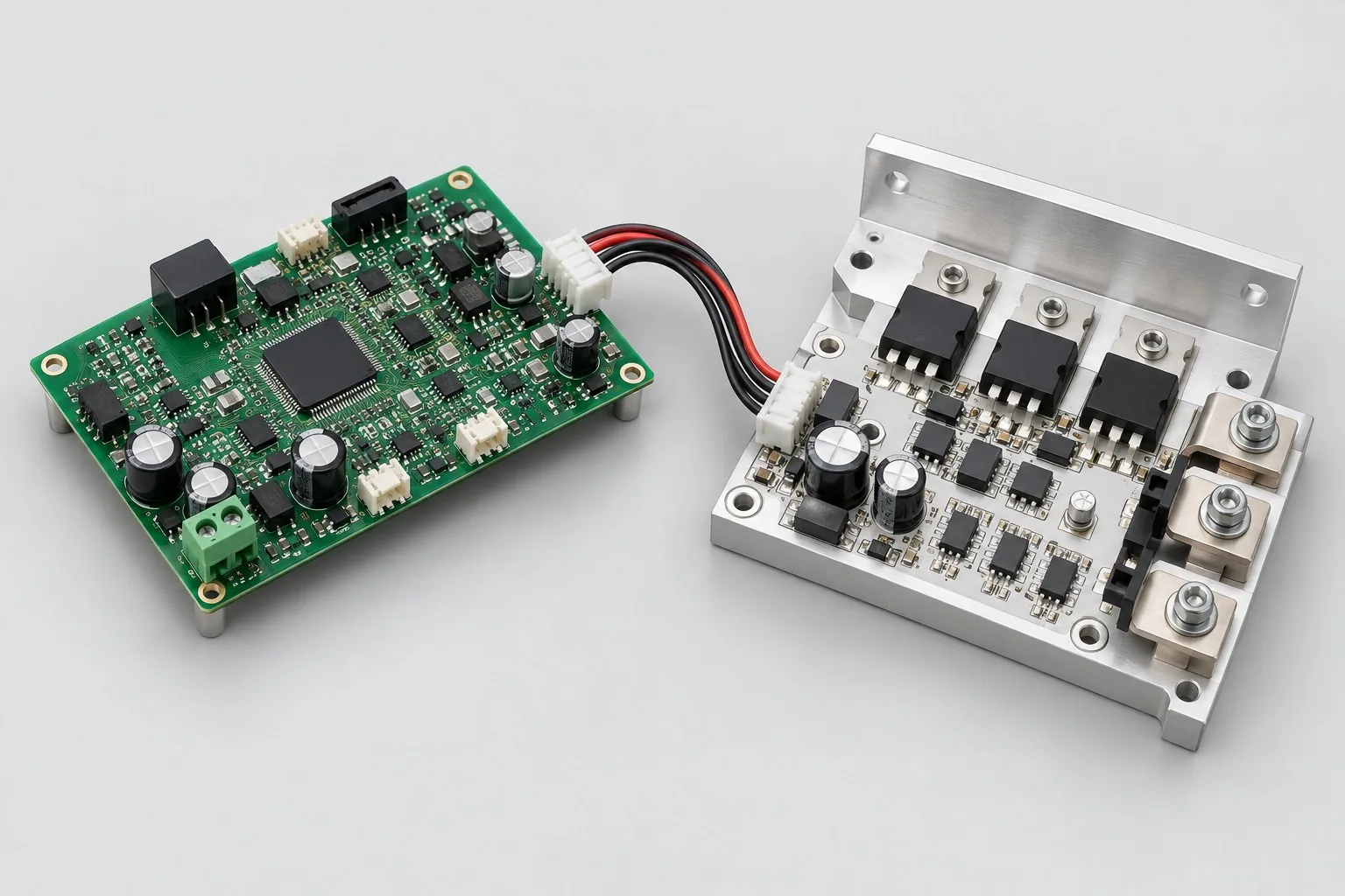
Can aluminum-core LED boards become 10A power switches?
Similar metal bases do not mean identical circuits. Switches need MOSFETs, drives, Kelvin current sensing, flyback, and protection. External-current LED structures cannot directly serve this. Reuse thermal concepts, but develop power/control interconnects as new tasks.
How should RFQ files be prepared for aluminum-core LED design?
Initially describe functions, uses, and files. Quotes confirm LED thermal resistance, forward-voltage drop and junction-temperature limits; sink three-dimensional model/force/interfaces/environment; insulation/lenses/holes. Provide editable schematics/PCB/BOM or fault-prototype revisions/reproduction records. List missing-data reviews to avoid differing assumptions.
How should aluminum-core LED verification costs be compared by condition?
Fix quantities, revisions, equipment, and criteria. Separately check thermal chains: fixed models/dielectrics/TIM/sinks/torque and actual current such as 700mA, measured points/maps; mounting sensitivity: fixed flatness/TIM/fastening, combination rises; optics/insulation: fixed strings/drives/requirements, approved-current light and standard-based insulation. Specify raw-data/issue-closure delivery. One power-on pass is not full verification.
Compare related designs and plan the next step
Separate power stage and IMS thermal board design
Return metal substrate design selection · Select solution by device function · Discuss your design requirements
Documentation Basis and Boundaries
Engineering reference | LM3409 selection conditions and board verification: LM3409 references external drives only. Review IMS paths/insulation; actual suppliers define dielectric/TIM values.
Engineering reference | PCB thermal structures: IMS, thermal vias, and embedded copper: IMS/thermal methods; material parameters follow selected suppliers/grades.