Engineering Reference Configuration
Industrial communication PCB assembly: configuration, testing, and deliverables
The following adjustable engineering configurations support material, functional, and process review; they are not stocked models or commitments to current production-line capabilities. Approved fabrication documentation and order acceptance requirements govern.
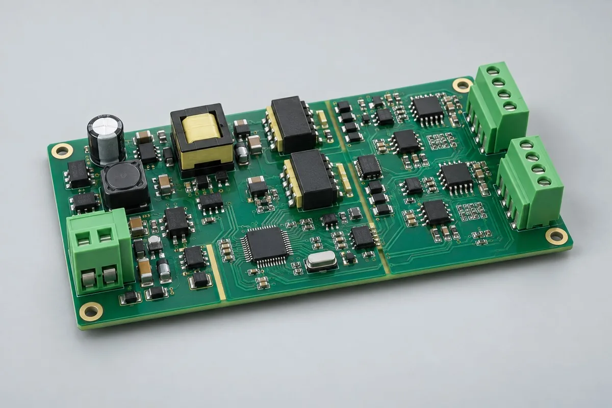
Industrial communication PCB assembly supports contract manufacturing and procurement review for dual RS-485 or CAN conversion. First confirm MCU + isolated transceivers + surge-protection options, 2 fieldbus ports and USB/UART maintenance ports, and 4-layer FR-4 with defined isolation regions and return paths. Then compare SMT → terminal secondary soldering → insulation-region inspection → protocol testing scope and acceptance costs for port loopback, bus communication, disconnection/recovery, and isolation. This page distinguishes interface board + address list + protocol/test revisions from separate RS-485 and CAN BOMs that are not automatically interchangeable, helping assess whether quotations cover actual use. RFQ information reference:BOM · bare board · material supply
Reference specification and configuration options
| Options | Reference Configuration |
|---|---|
| Power and Logic Domains | 24V input; isolated DC/DC on logic side |
| Functional Module | Dual RS-485 or CAN communication conversion |
| Core Components/Architecture | MCU + isolated transceivers + surge-protection options |
| Interface and Channels | 2 fieldbus ports; USB/UART maintenance ports |
| Board Layers and Material Options | 4-layer FR-4; defined isolation regions and return paths |
| Component types | SMD MCU/isolators, DC/DC modules, through-hole terminals |
| Assembly Route | SMT → terminal secondary soldering → insulation-region inspection → protocol testing |
| Material Supply Scope | Specified transceivers/isolators; locked mating terminal part numbers |
| Firmware and Parameters | Baud rate, address, protocol mapping, and upgrade revisions |
| Test Focus | Port loopback, bus communication, disconnection/recovery, isolation items |
| Deliverables | Interface board + address list + protocol/test revisions |
| Configuration Limits/Options | Separate RS-485 and CAN BOMs; not automatically interchangeable |
How much does industrial communication PCB assembly cost, and what does the quotation include?
Isolated transceivers, DC/DC, protection components, and terminals determine communication-board costs; dual-bus secondary soldering, software/address programming, insulation-region inspection, and disconnection recovery each involve work. RS-485 and CAN versions have different BOMs, and fixed versus configurable termination have different assembly and error-proofing needs. Interface count alone cannot determine pricing.
Quotation terms depend on the approved files, quantity, material supply, tests and delivery requirements.
Prepare a structured RFQ or use the short inquiry form.
| Cost Item | Scope for This Configuration | Billing frequency and work scope | Procurement Verification |
|---|---|---|---|
| Bare PCB and core components | MCU + isolated transceivers + surge-protection options; 4-layer FR-4; defined isolation regions and return paths | Price according to actual bare-board/component purchase quantities; authorize critical components and substitutions individually | Specified transceivers/isolators; locked mating terminal part numbers |
| Placement and Post-Assembly | SMT → terminal secondary soldering → insulation-region inspection → protocol testing | Feeder/program setup per lot; assembly priced per board, joint, or process as agreed, with counting rules specified | SMD MCU/isolators, DC/DC modules, through-hole terminals |
| Manufacturing Preparation | Review stencils, first articles, and support tooling against the actual assembly route | New stencils/carriers may be separate one-time charges; verify panelization, revision, and condition before reuse | Reduced quantities do not automatically eliminate first-article or feeder setup |
| Functional Support | Port loopback, bus communication, disconnection/recovery, isolation items | Itemize test-method/fixture/script setup; agree execution charges per board, channel, or test duration | Separate supporting development from execution records for each board |
| Software and Parameters | Baud rate, address, protocol mapping, and upgrade revisions | When firmware exists, distinguish file programming/verification from software development; omit programming without a firmware revision | Customer-approved files, parameters, and readback rules determine scope |
| Delivery and Change | Interface board + address list + protocol/test revisions; separate RS-485 and CAN BOMs, not automatically interchangeable | Price accessories, retesting, and revision changes by approved work items; do not prefill fixed rates | Check BOM, tooling, programs, and acceptance revisions before reorders |
How do RS-485 and CAN communication boards differ?
Transceivers, electrical interfaces, and protocol mechanisms differ; software changes alone cannot interchange them. Check field-device buses, topology, and address management before choosing versions. For Ethernet forwarding or system services, compare complete gateway mainboards.
| Comparison Metric | Current Conditions | Factors Influencing Procurement Decision |
|---|---|---|
| Manufacturing Delivery | SMT → terminal secondary soldering → insulation-region inspection → protocol testing | Produce boards/assemblies per BOM and assembly drawings; this does not establish that every system function passes |
| Functional Acceptance | Port loopback, bus communication, disconnection/recovery, isolation items | Compare unit prices after defining test stimuli, limits, accessories, and records; review missing test inputs first |
| Configuration Options | 2 fieldbus ports; USB/UART maintenance ports; 4-layer FR-4; defined isolation regions and return paths | Confirm circuit/program compatibility before reviewing assembly and test costs for interface, stackup, or component changes |
| Delivery Scope | Separate RS-485 and CAN BOMs; not automatically interchangeable | Complete-system accessories, application development, and project verification are not automatically included in board assembly |
Do industrial communication boards need isolation and configurable termination?
Define isolation boundaries from field grounding, potential differences, network topology, and system design. Fixed termination eliminates a setting step but cannot be installed indiscriminately at every node. Jumpers or DIP switches ease field configuration but require outgoing labels and error-proofing checks.
- First list the dual RS-485 or CAN conversion needed, distinguishing build-to-print manufacturing, configuration changes, and new-function development.
- Then freeze complete part numbers for MCU + isolated transceivers + surge-protection options, 2 fieldbus ports and USB/UART maintenance ports, and 4-layer FR-4 with defined isolation regions and return paths. Separate consigned and sourced materials using specified transceivers/isolators and locked mating terminal part numbers.
- Use first articles to check SMT → terminal secondary soldering → insulation-region inspection → protocol testing and baud rate, address, protocol mapping, and upgrade revisions. If only program files are supplied, agree on programming verification first; review development separately.
- Turn port loopback, bus communication, disconnection/recovery, and isolation into acceptance items with stimuli, limits, and records, specifying fixture ownership, per-board execution, and post-rework retests.
- Finally confirm interface board + address list + protocol/test revisions and separate RS-485/CAN BOMs that are not automatically interchangeable. Compare total prices at equal quantities, accessories, and test scope, and freeze order revisions.
Applicable uses and situations requiring separate review
Fieldbus conversion, industrial isolated communication, equipment networking interfaces.
High-speed Ethernet switching and wireless communication are outside this configuration. Systems approaching safety-related isolation must redefine insulation requirements against applicable standards; an isolator alone does not establish safety compliance.
Assembly Challenges for This Product
Visually inspect isolation slots, creepage regions, and solder near terminals; secondary-soldering splatter and cleaning residues may bridge design boundaries. Set termination resistors and bias networks by bus topology, distinguishing outgoing versions with labels to prevent excessive parallel termination in the field.
Structural, thermal, and configuration trade-offs
Fixed termination reduces assembly steps but limits topology; DIP switches or jumpers accommodate field use but add configuration error-proofing. Isolated-supply efficiency and ripple affect temperature rise and interface stability; check both buses communicating simultaneously.
Product-specific test matrix
| Test stage | Inspection/Functional Methods | Acceptance Record |
|---|---|---|
| Port Connectivity | Independent transmit/receive and loopback for each port | Port number, frame count, and errors |
| Network Anomaly | Line drop, brief power loss and post-recovery communication | Recovery Behaviors and Logs |
| Isolation Zone | Visually inspect cleanliness/spacing and perform electrical isolation tests to project specifications | Inspection records, conditions, and results |
Defect Handling and Acceptance
Reversed transceivers, incorrect termination, and duplicate addresses produce different communication faults. Acceptance requires boundary nodes and both ports operating together with controlled bus loads; one board's serial output cannot establish field compatibility.
Isolated communication PCB assembly: material supply and revision control
Transceivers differ in pinouts, common-mode ranges, and isolation ratings; interface names alone cannot justify substitutions. Customers provide protocol test messages and exception-handling rules; lock sourced isolated-supply revisions.
Prototyping vs. Production Differences
Assembly assumes defined buses, power isolation, termination, and address rules. In production, link parameters/addresses to board IDs and cover all populated ports with fixtures. Unlike this production scope, communication-interface validation prototypes explore interface/protocol boundaries using jumpers, termination, and transceiver variants and deliver issue/change lists; their debug software cannot directly serve as this page's shipping revision.
Delivery Configuration
Interface board + address list + protocol/test revisions. Separate RS-485 and CAN BOMs; not automatically interchangeable.
Convert this configuration into a reviewable order
For isolated industrial communication board orders, check BOM, quantity, material supply, and conditions below; add pick-and-place files/CPL, DNP items, and assembly drawings for SMT. For programming, provide files, programming rules, and checksums corresponding to baud rate, address, protocol mapping, and upgrade revisions. Review costs separately for materials, SMT → terminal secondary soldering → insulation-region inspection → protocol testing, and required stencils/line setup, support carriers, and test equipment. Reapprove revisions after documentation changes; agree on delivery milestones after kit completion and scheduling confirmation.
| Required project inputs | Engineering Decisions Affected | Records/delivery as agreed in the order |
|---|---|---|
| Communication Isolation on Both Sides | Provide the actual RS-485/CAN combination, termination resistors, baud rates, and supplies on both sides. | Record communication at each end, termination configurations, and isolated-supply checks; define isolation-withstand conditions separately. |
| Field Anomaly | Define disconnection, bus-occupancy, and power-loss recovery rules. | Link test logs to firmware; messages alone cannot establish correct operation of every protocol function. |
Industrial communication PCB assembly FAQ
How much does industrial communication PCB assembly cost, and what does the quotation include?
For standard placement, first calculate board quantity × billable points per board × price per point + setup fee. A project-specific quotation requires review of the available files, quantity, materials, requested tests, delivery destination, taxes, shipping, and trade terms. This is a placement-only reference; bare PCBs, materials, and testing are charged separately. Any formula on this page organizes cost inputs; it is not a quoted rate.View cost items, calculation conditions, and sources.
How do RS-485 and CAN communication boards differ?
Transceivers, electrical interfaces, and protocol mechanisms differ; software changes alone cannot interchange them. Check field-device buses, topology, and address management before choosing versions. For Ethernet forwarding or system services, compare complete gateway mainboards.
Do industrial communication boards need isolation and configurable termination?
Define isolation boundaries from field grounding, potential differences, network topology, and system design. Fixed termination eliminates a setting step but cannot be installed indiscriminately at every node. Jumpers or DIP switches ease field configuration but require outgoing labels and error-proofing checks.
Does a dual-port communication quotation include protocol-conversion software?
Customer-program programming, address configuration, and new-protocol development differ. List each port's messages, mapping, disconnection recovery, and upgrade tests in quotations; without protocol definitions, simple loopback testing cannot estimate complete application costs.
Is loopback testing on the communication board sufficient?
Loopback checks local links but does not cover field termination settings, disconnection recovery, or simultaneous dual-port communication. Record port results against approved messages and revisions so a working maintenance serial port does not hide bus problems.
Is installing termination resistors on both fieldbus channels always more reliable?
Follow network topology rather than adding termination unconditionally at every node. Distinguish fixed, jumper, and DIP-switch versions in quotations and assembly lists; outgoing markings should identify actual settings to prevent field/test mismatches.
Which address and protocol records do industrial communication boards need?
Retain each port's address, baud rate, mapping, and software revision, linked to approved messages and recovery results. Check both configurations separately; successful maintenance-port communication does not establish correct fieldbus configuration.
How should port-connectivity testing be included in industrial communication PCB assembly procurement acceptance?
The reference method independently transmits/receives and loops back each port; records include port numbers, frame counts, and errors. Provide test inputs, applicable configurations, and acceptance limits first, then agree on first-article validation and per-board execution scope. Price test preparation separately from each execution. Without limits, review methods first rather than labeling completed operations as specification compliance.
How should network-fault testing be included in industrial communication PCB assembly procurement acceptance?
The reference method disconnects links, briefly interrupts power, and checks communication after recovery; records include recovery behavior and logs. Provide test inputs, applicable configurations, and acceptance limits first, then agree on first-article validation and per-board execution scope. Price test preparation separately from each execution. Without limits, review methods first rather than labeling completed operations as specification compliance.
How should isolation-region testing be included in industrial communication PCB assembly procurement acceptance?
The reference method visually checks cleanliness/spacing and performs electrical isolation tests to project specifications; records include inspection records, conditions, and results. Provide test inputs, applicable configurations, and acceptance limits first, then agree on first-article validation and per-board execution scope. Price test preparation separately from each execution. Without limits, review methods first rather than labeling completed operations as specification compliance.
When the customer supplies software, how should programming and development be priced separately for industrial communication PCB assembly?
Controlled content covers baud rate, address, protocol mapping, and upgrade revisions. Programming approved customer files, loading parameters, and readback verification are manufacturing execution; new logic, interface adaptation, or algorithm changes require development review. List preparation, per-board programming, verification, and failure handling separately; including programming does not imply application development is included.
Must first-article, stencil, and line-setup charges be recalculated for repeat industrial communication PCB assembly orders?
The route is SMT → terminal secondary soldering → insulation-region inspection → protocol testing. For SMT, check stencils and panels; for through-hole or later installation, check support and assembly methods. Agree on setup and first articles for this batch; reuse old tooling only when revision, location, and condition match. After changing SMD MCU/isolators, DC/DC modules, through-hole terminals, or interfaces, review tooling effects and port loopback, bus communication, disconnection/recovery, and isolation before confirming recurring charges.
How should total industrial communication PCB assembly prices be compared when critical components are consigned and others sourced?
Build a procurement responsibility table using specified transceivers/isolators and locked mating terminal part numbers. Confirm complete part numbers, quantity, packaging, and excess-material rules with materials. Consignment only changes procurement boundaries; SMT → terminal secondary soldering → insulation-region inspection → protocol testing and port loopback, bus communication, disconnection/recovery, and isolation remain actual work. Approve shortage, substitution, or batch-change impacts first; consigned-material unit prices cannot be compared directly with material-inclusive assembly totals.
Which items need retesting after industrial communication PCB assembly rework or supplemental orders?
Select retests by change impact. Original acceptance covers port loopback, bus communication, disconnection/recovery, and isolation; shipping records comprise interface board + address list + protocol/test revisions. If repairs affect power, interfaces, critical analog circuits, or software revisions, check related tests rather than repaired joints alone. Align supplemental orders with original BOM, parameters, and test equipment. Agree on retest costs by approved items and actual quantity, without assuming free service or fixed turnaround.
Compare Other Products in This Category
- 8 channel AD detection module: engineering reference; define measurement ranges, sampling, interfaces and calibration for the actual project.
- Communication interface validation prototype: termination/isolation/jumper variants, delivering messages and revision issues.
Return to industrial-control PCB assembly configuration comparison · Component Supply and Procurement · Testing and Delivery Scope
Material and Process Reference
- Engineering reference | SMT packages and assembly methods: pads, stencils, and thermal processes: a package/assembly method index only; not evidence that the product configurations on this page are models produced by KFPCBA