Engineering Selection Reference
RO4003C hybrid board: four-layer RO4003C hybrid fabrication review
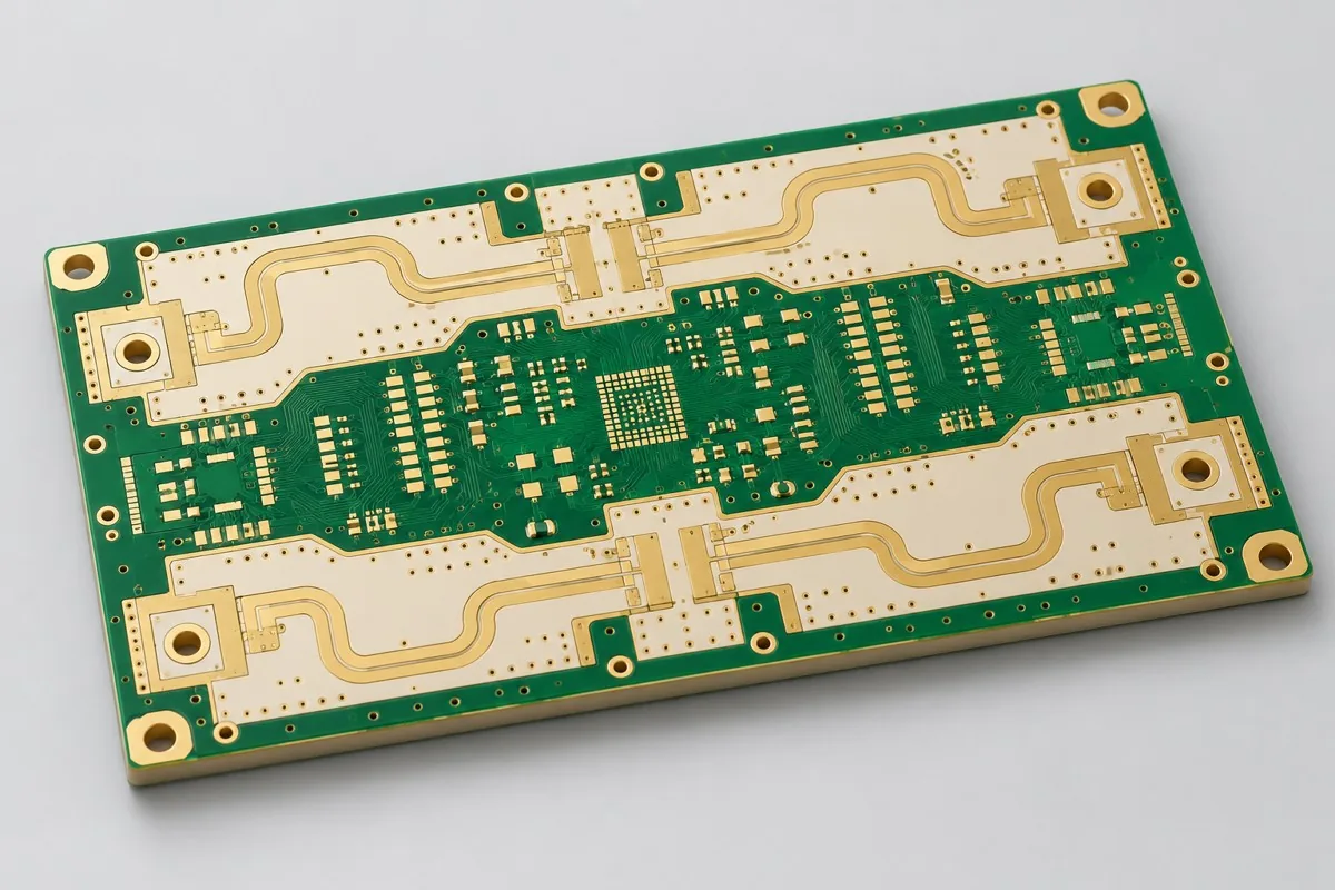
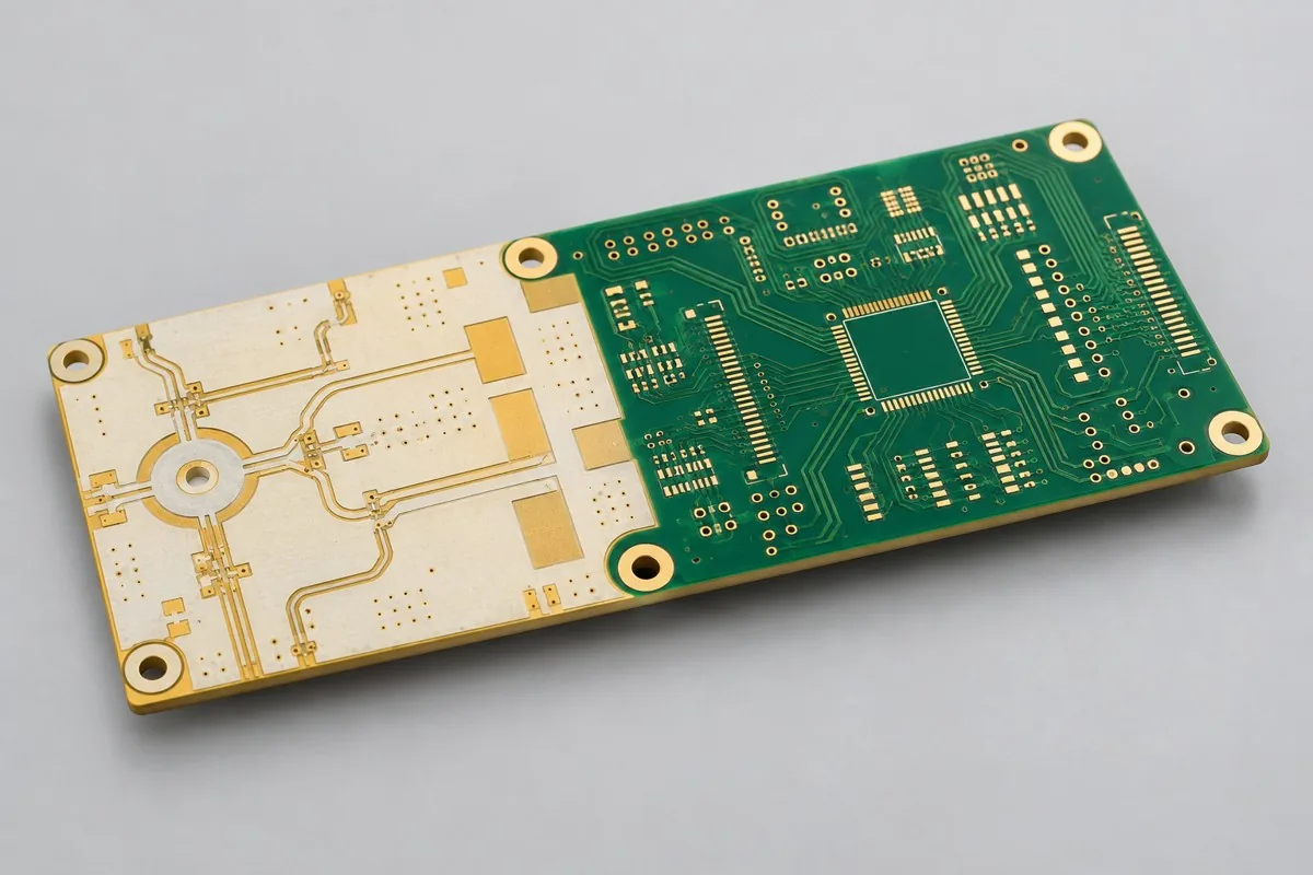
Four-layer RO4003C hybrid-board fabrication requires review against current drawings. For four-layer RO4003C analog-control hybrid bare boards, specify RF cores, FR4, and bonding sheets by layer. A single RF side reduces specialty-material usage but also requires assessment of lamination asymmetry; deliver the approved Layer Stackup and interface-inspection scope, with the reference structure finalized after material-combination review.
For RO4003C hybrid boards, first define bare-board prototyping or production scope. Please provide Gerber, drill files, stackup, materials/processes, quantity, and manufacturing acceptance requirements. Four-layer single-sided RF hybrid construction reduces specialty-material layers, with limited digital density
Four-layer RO4003C hybrid-board review first checks layer allocation of RO4003C and 370HR; quotation documentation also needs RF regions and FR4/bonding-sheet lists. Subsequent specification and manufacturing-input tables link critical design targets to inspection methods.
Why choose this single-RF-side hybrid structure
Tunable filters or analog front ends with low-speed control can start with four-layer single-sided RO4003C hybrid construction. The top layer handles RF, with an internal ground reference and lower FR4 handling power/control. When digital BGA density is low, this avoids upgrading to six or eight layers for a few control traces.
How should four-layer RO4003C hybrid-board quotations be itemized?
Separate RF cores, FR4 and bonding materials, four-layer lamination and drilling/plating, surface finish, and interface/warpage checks. Specialty material on one side reduces usage but adds control work for material combinations and asymmetric copper distribution. Compare all-RO4003C and hybrid quotes with the same RF dielectric thickness, outline, and acceptance scope; less material does not imply proportional price reduction.
Quotation terms depend on the approved files, quantity, material supply, tests and delivery requirements.
Prepare a structured RFQ or use the short inquiry form.
Enter the following items in one itemized quotation: specify cost units and tax/shipping basis, with separate columns for first orders and same-revision repeat orders. The table is a procurement breakdown method, not a ready-made price list; reference specifications require approval against current fabrication drawings.
| Quotation items and pricing boundaries | Actual inputs requiring alignment for this model | Repurchase of same version and change boundaries |
|---|---|---|
| Materials/fabrication, quoted per batch or accepted board | RO4003C single-sided RF core+370HR FR4; 4 layers; RF base copper 18µm/finished 35µm; inner copper target 35µm | Recurs on repeat orders; material, layer-order, or copper-weight changes require requotation |
| Holes and forming, per approved hole table | Ø0.30mm through holes; no blind vias | Reorders follow the same revision; review operations before changing RF and analog regions |
| Surface finish/packaging, noting areas and batches | Silver immersion; keep standard solderable areas on pads | Incurred by actual batch; confirm packaging, storage conditions, and surface-finish substitutions separately |
| Engineering/tooling preparation, identifying one-time or per-batch charges | RF and analog regions: provide RF-layer artwork, analog reference ground, and cross-region connections; determine RO4003C/FR4 lamination sequence. | Verify file revisions, ownership, and storage condition before reusing old tooling; do not assume reuse is free |
| Structural/special inspections, identifying coupons, hole groups, or samples | Deliver approved stackup, cross-region return-path review, and sampling conditions for critical dielectric thickness. Material-combination approval records include cores, bonding sheets, and pressed dielectric-thickness targets. | List initial prototype validation and per-batch sampling separately; quote per-board requirements separately rather than assuming everything is completed once |
| Delivery scope, listing reports and pass quantity | Four-layer hybrid bare PCB, layer-by-layer material list, thickness/layer-sequence files, and warpage/dimensional records; optional RF coupons and first-article interface microsections. | Retain revision links and batch records on repeat orders; list component assembly, firmware, and complete-unit testing separately |
How do four-layer single-RF and eight-layer dual-RF hybrid boards differ?
The four-layer option separates one RF side, continuous reference ground, and low-speed control, suiting tunable-filter control boards with low digital density. The eight-layer dual-RF option gives ports on both sides their own ground references and adds digital layers. A short RF path on one side does not require paying for dual RF cores; many RF ports on both sides should not be forced into four layers.
| Comparison Dimension | RO4003C hybrid-material PCB fabrication | RO4350B eight-layer hybrid PCB |
|---|---|---|
| Material and Grade | RO4003C single-sided RF core+370HR FR4 | RO4350B RF cores on both sides+370HR FR4 center core |
| Layer Count and Structure | 4 Layer | 8 Layer |
| Hole Structure and Dimensions | Ø0.30mm through holes; no blind vias | Ø0.30mm through holes; top/bottom RF port transitions simulated separately |
| Application | Tunable RF filter control boards; low-speed analog measurement front ends | Dual-channel wireless transceivers; multiband test instruments |
Can hybrid PCB materials change while total thickness remains unchanged?
Equal total thickness does not mean equal RF conditions. Maintain dielectric thickness and copper weight from L1 to RF reference ground first, then check FR4, bonding layers, and symmetric thickness allocation. Changing RO4003C thickness alters feedline geometry and lamination relationships. A layer-by-layer material table stabilizes quotes and reorder revisions better than simply specifying a four-layer hybrid board.
| Decision Sequence | This Model Input | Generated Auditable Output |
|---|---|---|
| 1 define usage and boundaries first | Provide RF-layer artwork, analog reference ground, and cross-region connections; determine RO4003C/FR4 lamination sequence. | Deliver approved stackup, cross-region return-path review, and sampling conditions for critical dielectric thickness. |
| 2 fixed conditions affecting structure | List permitted FR4 and bonding-material alternatives; do not quote only by two core names. | Material-combination approval records include cores, bonding sheets, and pressed dielectric-thickness targets. |
| 3 Align Networks with Manufacturing Targets | RF 50Ω; no separate impedance specification for low-speed control; RF-trace TDR+port VNA | Provide target nets, layer pairs, and verification scope; review together with Ø0.30mm through holes and no blind vias |
| 4 then verify quotation and release | RO4003C single-sided RF core+370HR FR4; 1.20mm reference target; immersion silver, retaining conventional solderable pad areas | Request quotations using material/pattern/inspection lists at the same revision; list unapproved substitutions as separate alternatives rather than including them in the baseline quotation |
Single-RF-side hybrid bare-board manufacturing specifications
| Specification Items | Clarify Configuration/Target |
|---|---|
| Material and Grade | RO4003C single-sided RF core+370HR FR4 |
| Layer Count and Structure | 4 Layer |
| Total Board Thickness | 1.20mm reference target |
| Dielectric thickness and interlayer relationship | L1-L2 RO4003C 0.203mm; central FR4 bonding layer target 0.25mm |
| Base Copper and Finished Copper | RF base copper 18µm/finished 35µm; inner copper target 35µm |
| Hole Structure and Dimensions | Ø0.30mm through holes; no blind vias |
| Trace Width and Spacing | 0.15/0.15mm reference minimum design |
| Impedance Target and Measurement Methods | RF 50Ω; no separate impedance specification for low-speed control; RF-trace TDR+port VNA |
| Surface Finish | Silver immersion; keep standard solderable areas on pads |
| Original Material Specifications | RO4003C: process Dk 3.38±0.05, design Dk 3.55; Df 0.0027 (10GHz, manufacturer typical value); non-flame-retardant material |
| Application | Tunable RF filter control boards; low-speed analog measurement front ends |
| Deliverables | Four-layer hybrid bare PCB, layer-by-layer material list, thickness/layer-sequence files, and warpage/dimensional records; optional RF coupons and first-article interface microsections. |
Layer stackup and hole structure for single RF side mixed lamination board
The following shows functional layer order/material structure for this reference configuration, not a production stackup drawing; do not infer thickness from graphic proportions. Match copper-layer numbering to via layer pairs item by item in approved fabrication files.
| Top to Bottom | Layer Responsibilities/Structure |
|---|---|
| L1 | RF/Components |
| L2 | RF Ground |
| L3 | Low-Speed Control/Power Supply |
| L4 | Low-Speed Control/Components |
Hole structure: Ø0.30mm through holes; no blind vias
RO4003C and 370HR dielectric and loss models
RO4003C process Dk supports material comparison; transmission-line or resonant models use design Dk applicable to their frequency and method. Freeze procurement thickness, copper foil, and finish revisions together. Return measured first-article geometry to design for review; material Df is only an input to the loss budget.
Tradeoffs between reduced RF material and single-sided lamination warpage
Reducing specialty-material usage does not reduce process costs linearly with layer count. A specialty core on one side increases material asymmetry and requires lamination-warpage assessment. Projects with RF ports on both sides or high-speed digital buses should select dual-RF-side/six-layer function-integrated structures.
Frozen RF dielectric thickness and hybrid-material dimensional scaling: manufacturing checks
Freeze dielectric thickness from RO4003C to reference ground first, then adjust total thickness through FR4 layer allocation; RF dielectric thickness must not serve as filler. Processes must control differential dimensional scaling and resin bonding; circuit design defines grounding between RF and analog-control regions.
Material-interface microsections and warpage checks: acceptance items
Inspect first-article warpage, layer registration, and interface microsections. Verify RF ports by VNA; later assembled prototypes perform analog-control functional tests. Bare-board delivery covers only agreed electrical connections, dimensions, and material records, not automatic PCB assembly functional acceptance.
Single-RF-side hybrid bare-board delivery scope
Applications: tunable RF filter control boards; low-speed analog measurement front ends.
Four-layer hybrid bare PCB, layer-by-layer material list, thickness/layer-sequence files, and warpage/dimensional records; optional RF coupons and first-article interface microsections.
RF regions, FR4, and bonding-sheet list: quotation inputs
Submit RF regions and FR4/bonding-sheet lists, converting tabled design targets into inspectable fabrication drawings. The following inputs separately define artwork, material, or structural inspection scope; freeze the quotation revision with approved drawings.
| Inputs required to be completed for this product | Engineering Decisions Affected | Records/delivery as agreed in the order |
|---|---|---|
| RF and Analog Areas | Provide RF-layer artwork, analog reference ground, and cross-region connections; determine RO4003C/FR4 lamination sequence. | Deliver approved stackup, cross-region return-path review, and sampling conditions for critical dielectric thickness. |
| Mixed Lamination Procurement | List permitted FR4 and bonding-material alternatives; do not quote only by two core names. | Material-combination approval records include cores, bonding sheets, and pressed dielectric-thickness targets. |
RO4003C hybrid-material PCB fabrication: pricing, selection, and procurement FAQ
How should four-layer RO4003C hybrid-board quotations be itemized?
A project-specific quotation requires review of the available files, quantity, materials, requested tests, delivery destination, taxes, shipping, and trade terms. Add any specified processes and tests not yet included to the batch budget; a quotation for this configuration does not apply to other materials or layer sequences. Any formula on this page organizes cost inputs; it is not a quoted rate.View cost items, calculation conditions, and sources.
How do four-layer single-RF and eight-layer dual-RF hybrid boards differ?
Four-layer single-RF hybrid boards serve one RF side and lower-density control; eight-layer dual-RF boards provide ground references for top/bottom RF ports and additional digital resources. Evaluate four layers first when ports occupy one side; compare dual-RF structures for long RF paths on both sides or denser digital networks. View Specific Comparison Basis
Can hybrid PCB materials change while total thickness remains unchanged?
Equal total thickness alone does not justify substitution. Signal-to-ground dielectric thickness and Dk determine RF feedline geometry, while bonding materials and FR4 affect lamination adhesion. Freeze RF layer pairs first, allocate remaining thickness elsewhere, and recheck interfaces and warpage. View Specific Comparison Basis
Do low-speed control boards always need six-layer hybrid construction?
No. Four-layer single-RF construction can be verified first when control networks are sparse and RF reference ground remains continuous; compare six-layer function-integrated boards when MCU interfaces increase or separate digital reference layers are needed.
Should hybrid prototypes undergo material-interface microsectioning?
Material bonding and interlayer dielectric thickness are critical inspection objects for this structure. First-article acceptance can include interface microsections, warpage, and RF coupons; assembled functional continuity cannot replace microsection inspection.
How should changes be controlled when RO4003C hybrid prototypes move to production?
Retain approved revisions for cores, FR4, bonding sheets, pressed dielectric thickness, and copper distribution. Reassess RF trace widths and warpage verification for any substitution; identical Gerber files do not establish an unchanged material combination.
Which work can offset material savings from four-layer single-RF hybrid construction?
Fewer specialty-material layers still require control of RO4003C, FR4, bonding-sheet combinations, pressed dielectric thickness, and warpage. Request both RF material-usage plans and interface/warpage inspection scope. Cheaper materials without approved combinations do not establish lower total hybrid-board cost.
How are per-board and per-panel RO4003C hybrid PCB quotations converted?
Retain single-sided RF regions and cross-region reference planes in panelization; RF coupons must match RO4003C layer pairs. Confirm warpage acceptance condition together with the depanelization route. State deliverable finished boards per panel, purchased panel count, and individual-board/panel delivery condition. Divide actual panel fabrication charges by corresponding accepted finished-board count for per-board fabrication cost; list setup, specialized inspections, and packaging separately, without promising yield from theoretical utilization.
How should one-time first-order charges and reorder costs be separated for RO4003C hybrid PCB fabrication?
First confirm RF/analog-region and hybrid-material procurement documentation, specifying whether engineering, tooling, or test setup is charged once. Deliver approved stackup, cross-region return-path review, and critical dielectric-thickness sampling conditions. Verify approved files and ownership before tool reuse; current-batch materials, fabrication, and approved inspections still incur costs. List preparation repeated after changes separately rather than relying on the old total.
Can I obtain an RO4003C hybrid PCB budget before RF/analog-region documentation is complete?
Describe application, outline, quantity, and available drawings for a budget identifying gaps. Formal review requires RF-layer artwork, analog reference ground, cross-region connection positions, and RO4003C/FR4 lamination sequence. Deliverables are the approved stackup, cross-region return-path review, and critical dielectric-thickness sampling conditions. Confirm fabrication/inspection quotes after these conditions freeze. Initial inquiries need not include every file, but estimates do not cover undefined structures by default.
What must be reconfirmed when materials, hole tables, or installation conditions change on an RO4003C hybrid PCB reorder?
List permitted FR4 and bonding-material alternatives rather than quoting only two core names. Material-combination approvals include cores, bonding sheets, and pressed dielectric-thickness targets. Map changes to previous material/hole-table/mechanical files item by item to determine drawing, process, or measurement updates; unchanged product name and layer count do not establish identical reorder conditions.
If two RO4003C hybrid PCB quotes use the same material, which configurations still need comparison?
Compare approved RO4003C/370HR/bonding-sheet combinations, pressed RF dielectric thickness, and interface/warpage checks. Total thickness or the Rogers name alone misses interlayer differences in hybrid construction.
Which reports should link to board identifiers before RO4003C hybrid prototypes move to production?
Deliver approved stackup, cross-region return-path review, and critical dielectric-thickness sampling conditions. Material-combination approvals include cores, bonding sheets, and pressed dielectric-thickness targets. Link material lots, approved fabrication files, and these results to current sample identifiers; production uses the revision with issues closed. Old coupon/artwork reports support comparison but cannot replace current inputs; define uncovered complete-system objects separately.
When small-batch RO4003C hybrid PCB unit prices fall, how can I tell whether total procurement costs decreased?
For identical RF geometry, compare all-specialty and single-RF hybrid structures by separating material savings from added interface/warpage inspections. This establishes whether total order costs fall. Add setup, fabrication, agreed inspections, packaging, and shipping, then divide by accepted delivery quantity to compare equal-scope totals and per-board allocation. Use current quotations for amounts and rates; assume no fixed discount.
Single-RF-side hybrid boards compared with related board types
Current configuration distinction: four-layer single-sided RF hybrid construction reduces specialty-material layers, with limited digital density
- Eight-layer dual-RF-side RO4350B hybrid board — Dual RF sides and a symmetric center core support partitioned routing, avoiding forcing dual ports into a single-RF-layer design
- Ten-layer low-loss signal and heavy-copper power hybrid board — Different copper weights and materials serve signal and power functions; resin filling and symmetry are priorities
Mixed PCB complete product catalog · All PCB Products
Material and design basis for single-RF-side hybrid boards
- Engineering reference | RO4003C material: process Dk, design Dk, and flame-retardancy limits: Published manufacturer material data
- Engineering reference | Isola 370HR material: high Tg and frequency-dependent parameters: Published manufacturer material data
When citing these resources, record material revisions and design conditions for layer allocation of RO4003C and 370HR; first articles focus on interface microsections and warpage. After material, copper-weight, or hole-structure changes, update fabrication drawings and inspections before release.
Request Quote for This PCB Configuration: cite product ID 218, attach critical circuit/interface information and quantity, and list specifications to retain or adjust.