Engineering Selection Reference
RO4003C PCB: RO4003C microwave filter board fabrication review
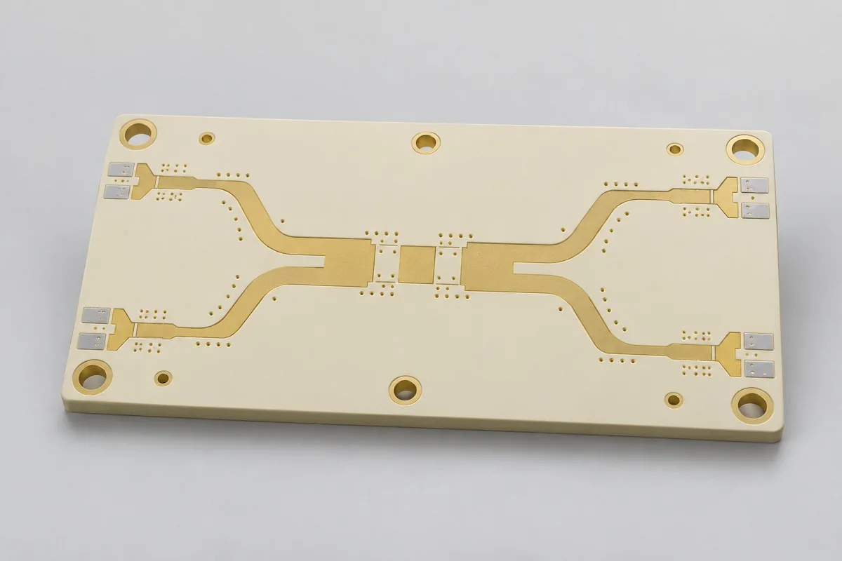
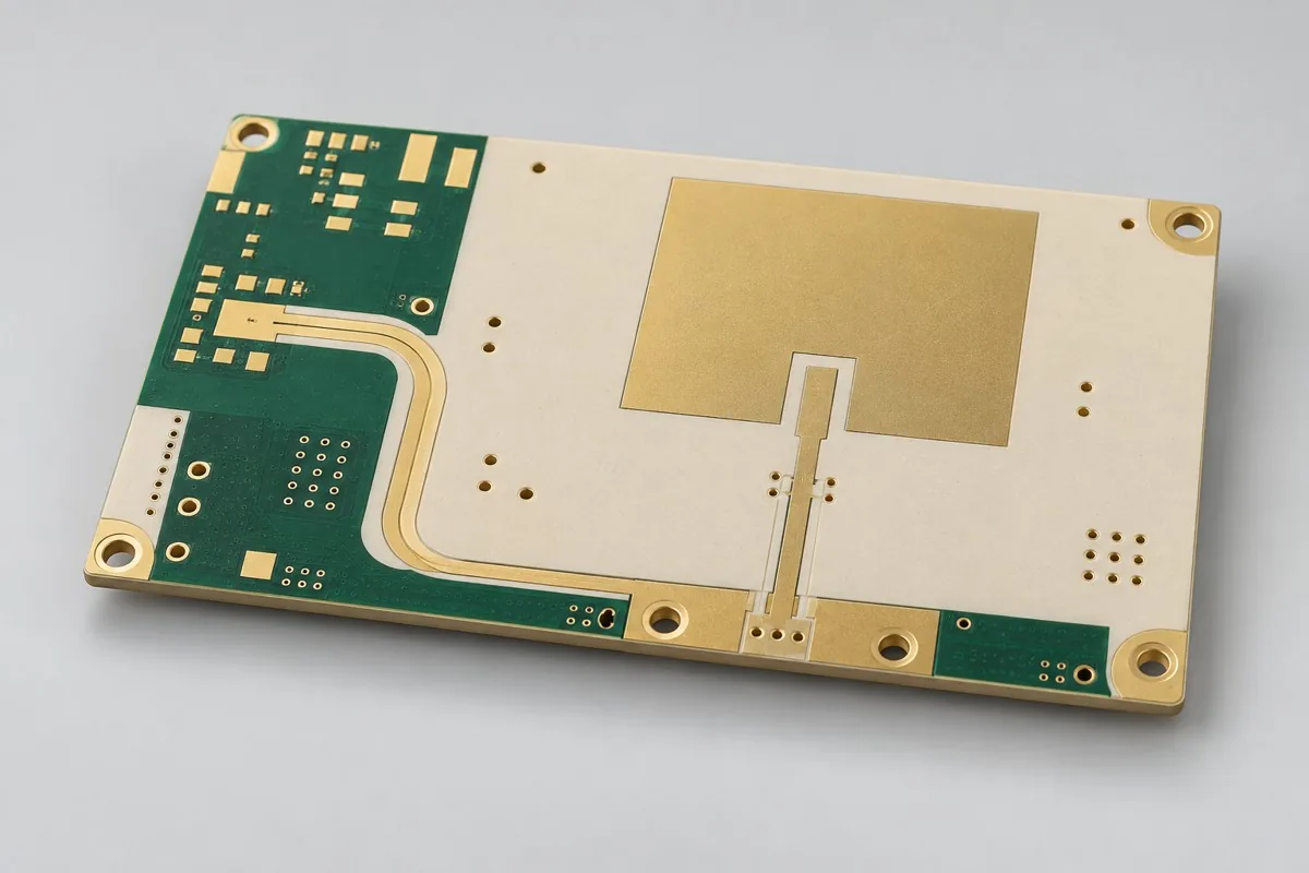
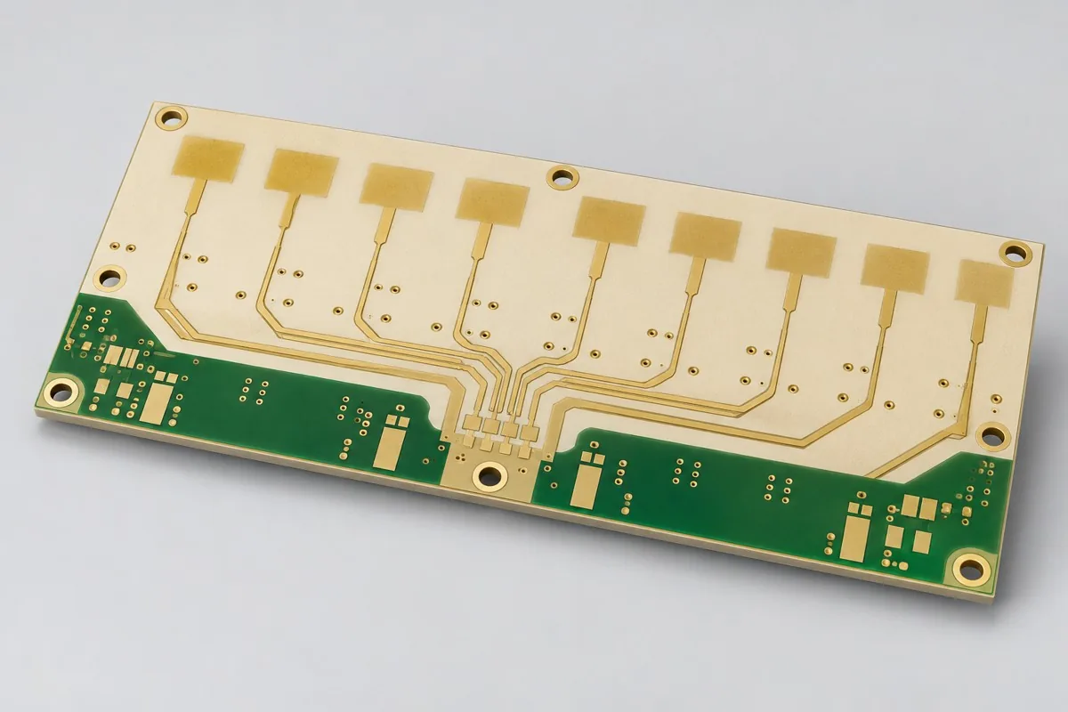
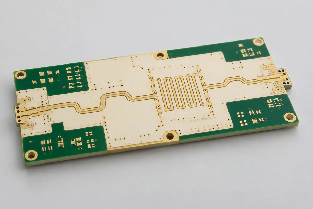
RO4003C microwave filter board fabrication requires review against the current fabrication drawings. Submit center frequency, bandwidth, and coupling-gap dimensional drawings for double-sided RO4003C filter boards. Review thicker dielectric and non-flame-retardant material limitations together; agree bare-board dimensional records separately from VNA curves measured with connector fixtures. This page is an adjustable Engineering Reference Configuration.
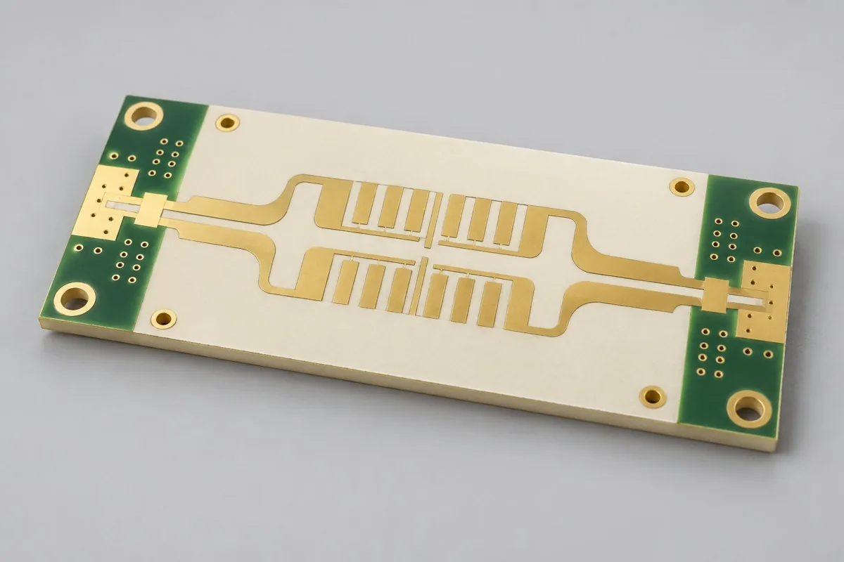
For RO4003C PCBs, first define bare-board prototyping or production scope. Please provide Gerber data, drill files, board outline, and layer stackup, materials and processes, quantity, and manufacturing acceptance requirements. This thicker double-sided RO4003C resonant structure focuses on coupling gaps and center frequency
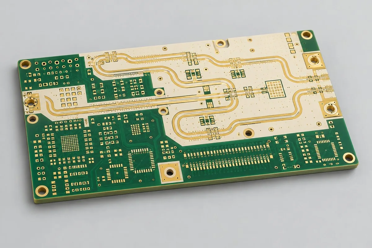
RO4003C microwave filter board review begins with the 0.813mm dielectric and resonant dimensions; quotation documentation also needs the filter frequency band and Material Substitution scope. Subsequent specification and manufacturing-input tables link critical design targets to inspection methods.
Why Choose This Structure for Microwave Filter Boards?
Double-sided RO4003C is an option when resonant lengths and coupling gaps determine filter or coupled-structure passbands. The 0.813mm dielectric provides a thicker microwave-structure starting point for comparing coupled-line geometries; this thickness should not be applied to every small RF module.
Why can't RO4003C high-frequency PCB prototyping prices be calculated by area alone?
Beyond material area, this 0.813mm double-sided RO4003C filter board requires dimensional control of coupling gaps and resonator ends, solder-mask-free windows, immersion-silver protection, and specified test structures. Narrow-gap inspection and VNA testing with connector fixtures are different tasks. List bare-board quantities, critical-dimension reports, and filter-curve scope separately to compare supplier quotes.
Quotation terms depend on the approved files, quantity, material supply, tests and delivery requirements.
Prepare a structured RFQ or use the short inquiry form.
Enter the following items in one itemized quotation: specify cost units and tax/shipping basis, with separate columns for first orders and same-revision repeat orders. The table is a procurement breakdown method, not a ready-made price list; reference specifications require approval against current fabrication drawings.
| Quotation items and pricing boundaries | Actual inputs requiring alignment for this model | Repurchase of same version and change boundaries |
|---|---|---|
| Materials/fabrication, quoted per batch or accepted board | Rogers RO4003C; 2 layers; base copper 35µm; finished copper target 35µm | Recurs on repeat orders; material, layer-order, or copper-weight changes require requotation |
| Holes and forming, per approved hole table | Ø0.30mm finished ground through-holes; keep unrelated holes out of resonant regions | Reorders follow the same revision; review operations before changing resonant/coupled artwork |
| Surface finish/packaging, noting areas and batches | Silver immersion; solder mask not covering resonant areas | Incurred by actual batch; confirm packaging, storage conditions, and surface-finish substitutions separately |
| Engineering/tooling preparation, identifying one-time or per-batch charges | Resonant/coupled artwork: provide center-frequency and bandwidth targets and critical coupling-gap dimensions; determine measurement locations and sampling methods for critical features. | Verify file revisions, ownership, and storage condition before reusing old tooling; do not assume reuse is free |
| Structural/special inspections, identifying coupons, hole groups, or samples | Agree delivery of measured critical-gap widths; separately specify connectors, fixtures, and calibration planes for filter curves. Record approved material revisions and modified drawings, not just Rogers. | List initial prototype validation and per-batch sampling separately; quote per-board requirements separately rather than assuming everything is completed once |
| Delivery scope, listing reports and pass quantity | Bare PCB, coupling-gap dimensional records, material lots, and approved simulation geometry; optional long/short lines and filter test structures on the same panel. | Retain revision links and batch records on repeat orders; list component assembly, firmware, and complete-unit testing separately |
Which is better: an RO4003C filter board or an RO4350B transceiver board?
Neither is universally better. The current RO4003C option is a thicker double-sided resonant structure requiring attention to passbands, coupling, and non-flame-retardant suitability; the RO4350B transceiver option uses different feedlines and dielectric thickness while addressing flame-retardant material needs. Compare filter geometry, thickness, and system requirements alongside materials; one Df value does not determine complete-board insertion loss.
| Comparison Dimension | RO4003C High-Frequency Board Prototyping | RO4350B high-frequency PCB fabrication |
|---|---|---|
| Material and Grade | Rogers RO4003C | Rogers RO4350B |
| Layer Count and Structure | 2 Layer | 2 Layer |
| Hole Structure and Dimensions | Ø0.30mm finished ground through-holes; keep unrelated holes out of resonant regions | Ø0.30mm finished through-holes; RF ground-via fence |
| Application | Microwave bandpass filters; coupler validation boards | Wireless transceiver modules; RF power-amplifier driver stages |
How should RO4003C filter board thickness and coupling spacing be selected?
Dielectric thickness affects transmission lines and coupling fields; coupling spacing and resonant length jointly affect center frequency, bandwidth, and return loss. Define frequency band and bandwidth first, then develop geometry using applicable design Dk and specify critical gap widths and measurement locations in fabrication drawings. Changing thickness to save material requires updated models and prototypes, not merely an unchanged board outline.
| Decision Sequence | This Model Input | Generated Auditable Output |
|---|---|---|
| 1 define usage and boundaries first | Provide center-frequency and bandwidth targets and critical coupling-gap dimensions; determine measurement locations and sampling methods for critical features. | Agree delivery of measured critical-gap widths; specify connectors, fixtures, and calibration planes separately for filter curves. |
| 2 fixed conditions affecting structure | Clarify whether RO4003C thickness/copper-foil revisions may be substituted; recalculate resonant lengths before substitution. | Record approved material revisions and modified drawings, not just Rogers. |
| 3 Align Networks with Manufacturing Targets | 50Ω ports; full-wave simulation of filter sections, VNA measurement | Provide target nets, layer pairs, and verification scope; review together with Ø0.30mm finished ground through holes and exclusion of unrelated holes from resonant areas |
| 4 then verify quotation and release | Rogers RO4003C; 0.88mm target (excluding solder mask); immersion silver; no solder mask over resonant areas | Request quotations using material/pattern/inspection lists at the same revision; list unapproved substitutions as separate alternatives rather than including them in the baseline quotation |
Microwave filter board manufacturing specification
| Specification Items | Clarify Configuration/Target |
|---|---|
| Material and Grade | Rogers RO4003C |
| Layer Count and Structure | 2 Layer |
| Total Board Thickness | 0.88mm target (excluding solder mask) |
| Dielectric thickness and interlayer relationship | 0.813mm core board |
| Base Copper and Finished Copper | Base copper 35µm; finished copper target 35µm |
| Hole Structure and Dimensions | Ø0.30mm finished ground through-holes; keep unrelated holes out of resonant regions |
| Trace Width and Spacing | 0.15/0.15mm reference minimum design; coupling gaps specified separately |
| Impedance target and measurement method | 50Ω ports; full-wave simulation of filter sections, VNA measurement |
| Surface Finish | Silver immersion; solder mask not covering resonant areas |
| Original Material Specifications | RO4003C: process Dk 3.38±0.05, design Dk 3.55; Df 0.0027 (10GHz, manufacturer typical value); non-flame-retardant material |
| Application | Microwave bandpass filters; coupler validation boards |
| Deliverables | Bare PCB, coupling-gap dimensional records, material lots, and approved simulation geometry; optional long/short lines and filter test structures on the same panel. |
Microwave filter layer stackup and via structure
The following shows functional layer order/material structure for this reference configuration, not a production stackup drawing; do not infer thickness from graphic proportions. Match copper-layer numbering to via layer pairs item by item in approved fabrication files.
| Top to Bottom | Layer Responsibilities/Structure |
|---|---|
| L1 | Resonant/Coupling Patterns |
| L2 | Reference Ground |
Hole structure: Ø0.30mm finished ground through holes; unrelated holes prohibited in resonant areas
RO4003C dielectric and loss models
RO4003C process Dk supports material comparison; transmission-line or resonant models use design Dk applicable to their frequency and method. Freeze procurement thickness, copper foil, and finish revisions together. Return measured first-article geometry to design for review; material Df is only an input to the loss budget.
RO4003C non-flame-retardant application boundaries and cost tradeoffs
RO4003C material-loss data can inform budgets, but filter loss also includes copper surfaces, conductor length, and connectors. The manufacturer classifies it as non-flame-retardant; products requiring a UL94 V-0 material system should compare RO4350B and check the complete board's material combination.
Coupling-gap and resonator-end compensation: manufacturing checks
Separate etch compensation for narrow coupling gaps, resonator ends, and corners from ordinary digital traces. Solder-mask-free openings should extend beyond the effective resonant area without uneven edges; board-edge datums must support repeatable connector-fixture installation.
S21, S11, and passband center frequency: acceptance items
Beyond bare-board electrical testing, sample-check resonant lengths, coupling gaps, and dielectric thickness. VNA records should include at least S21, S11, and passband center/bandwidth. Compare first articles and later batches using the same fixture and de-embedding method, with values defined by filter design; material Df cannot directly establish insertion loss.
Microwave filter board delivery scope
Applications: microwave bandpass filters; coupler verification boards.
Bare PCB, coupling-gap dimensional records, material lots, and approved simulation geometry; optional long/short lines and filter test structures on the same panel.
Filter frequency band and material-substitution scope: quotation inputs
Submit the filter frequency band and material-substitution scope, turning tabled design targets into inspectable fabrication drawings. The following inputs separately define artwork, material, or structural inspection scope; freeze the quotation revision with approved drawings.
| Inputs required to be completed for this product | Engineering Decisions Affected | Records/delivery as agreed in the order |
|---|---|---|
| Resonant/Coupling Patterns | Provide center-frequency and bandwidth targets and critical coupling-gap dimensions; determine measurement locations and sampling methods for critical features. | Agree delivery of measured critical-gap widths; specify connectors, fixtures, and calibration planes separately for filter curves. |
| Material and Frequency Deviation | Clarify whether RO4003C thickness/copper-foil revisions may be substituted; recalculate resonant lengths before substitution. | Record approved material revisions and modified drawings, not just Rogers. |
RO4003C high-frequency PCB prototyping: pricing, selection, and procurement FAQ
Why can't RO4003C high-frequency PCB prototyping prices be calculated by area alone?
A project-specific quotation requires review of the available files, quantity, materials, requested tests, delivery destination, taxes, shipping, and trade terms. Add any specified processes and tests not yet included to the batch budget; a quotation for this configuration does not apply to other materials or layer sequences. Any formula on this page organizes cost inputs; it is not a quoted rate.View cost items, calculation conditions, and sources.
Which is better: an RO4003C filter board or an RO4350B transceiver board?
Neither is better independently of application: the current RO4003C board focuses on resonant lengths and coupling, while the RO4350B transceiver board focuses on feedlines and ports. Check frequency band, bandwidth, and flame-retardant material requirements first; lower material Df does not necessarily mean lower complete-filter insertion loss. View Specific Comparison Basis
How should RO4003C filter board thickness and coupling spacing be selected?
Define center frequency and bandwidth first, then calculate resonant lengths and coupling gaps using design Dk and dielectric thickness. 0.813mm is this configuration's reference starting point; thickness changes alter transmission and coupling fields, so an unchanged outline does not justify reusing old geometry. View Specific Comparison Basis
Can an RO4003C board be replaced by same-size FR4?
An identical outline does not justify direct substitution. Dielectric and loss changes affect resonant frequency and coupling; comparable samples require redesign. Confirm permitted frequency shifts and insertion-loss budgets first.
Does an RO4003C filter board quotation include connectors?
List bare-board fabrication separately from connector assembly. For filter testing, specify who supplies connectors, fixtures, and calibration standards, and agree reference planes so connector-free bare-board prices are not compared with complete test assemblies.
Why has an RO4003C prototype's center frequency shifted?
Compare actual dielectric thickness, coupling gaps, and resonant dimensions first, then check connector fixtures against model reference planes. Investigate material Dk, finish, and solder-mask changes individually; compliant laminate alone does not establish filter response.
Can critical-dimension reports and filter testing for an RO4003C board be procured in two rounds?
You can first procure bare boards and measured coupling-gap/resonator dimensions, compare actual geometry with the model, and then decide on connector-equipped VNA testing. Retain test structures and fixture datums in the first round; adding connectors or changing ports in the second round would otherwise make the results incomparable.
How are per-board and per-panel RO4003C prototype quotations converted?
Retain resonator ends, critical coupling gaps, and measurement structures in the approved panel; do not remove filter ports or trimming space to fit another board. State deliverable finished boards per panel, actual purchased panel count, and individual-board/panel delivery condition. Calculate fabrication cost per board by dividing actual panel fabrication charges by corresponding accepted finished-board count; list setup, specialized inspections, and packaging separately, without promising yield from theoretical utilization.
How should one-time first-order charges and reorder costs be separated for RO4003C prototypes?
First confirm resonant/coupled artwork and material/frequency-deviation documentation, stating whether engineering, tooling, or test setup is charged once. Agree measured critical-gap width records; separately specify connectors, fixtures, and calibration planes for filter curves. Verify approved files and ownership before reusing tools; current-batch materials, fabrication, and approved inspections still incur costs. List renewed preparation caused by changes separately rather than relying on the old order total.
Can I obtain an RO4003C prototype budget before resonant/coupled artwork is complete?
Describe application, board outline, quantity, and available drawings to obtain a budget identifying gaps. Formal review requires center-frequency and bandwidth targets, critical coupling-gap dimensions, and measurement locations and sampling methods. Corresponding deliverables are measured critical-gap widths, with connectors, fixtures, and calibration planes separately defined for filter curves. Confirm fabrication/inspection quotes after freezing these conditions. Initial inquiries need not include every file, but estimates do not cover undefined structures by default.
What must be reconfirmed when materials, hole tables, or installation conditions change on an RO4003C prototype reorder?
Clarify whether RO4003C thickness/copper-foil revisions may be substituted; recalculate resonant lengths first. Record approved material revisions and modified drawings, not just Rogers. Map changes to previous material/hole-table/mechanical files item by item to determine drawing, process, or measurement updates; retaining only product name and layer count does not establish identical reorder conditions.
If two RO4003C prototype quotes use the same material, which configurations still need comparison?
Focus on inspection tolerances for the 0.813mm core and resonant/coupled geometry. Separate bare-board dimensional records from fixture-based filter curves; identical grades do not mean both suppliers measured the same structure.
Which reports should link to board identifiers before RO4003C prototypes move to production?
Agree measured critical-gap width records, with connectors, fixtures, and calibration planes listed separately for filter curves. Record approved material revisions and modified drawings, not just Rogers. Link material lots, approved fabrication files, and inspection results to current sample identifiers; production uses the revision with issues closed. Reports for old coupons or artwork support comparisons but cannot replace current manufacturing inputs; define uncovered complete-system objects separately.
When small-batch RO4003C prototype unit prices fall, how can I tell whether total procurement costs really decreased?
Use bare boards plus measured coupling gaps as the base package, with fixture/connector-based filter curves as the verification package; distinguish quantity effects from removing the filter package. Add setup, fabrication, agreed inspections, packaging, and shipping, then divide by accepted delivery quantity to compare equal-scope totals and per-board allocation. Use current quotations for amounts and rates; assume no fixed discount.
Compare Microwave Filter Boards with Adjacent Board Types
Current configuration distinction: thicker double-sided RO4003C resonant structure focusing on coupling gaps and center frequency
- RO4350B double-sided RF transceiver board — Double-sided RO4350B, addressing RF through-hole fabrication and flame-retardant material needs
- RT/duroid 5880 low-Dk patch antenna board — Low-Dk PTFE radiating structure, with dimensions and hole treatment different from double-sided filter boards
- RO3003 thin-dielectric 24GHz radar antenna board — Thin ceramic-filled PTFE dielectric addressing fabrication deviations in 24GHz feedlines/arrays
- RO4835 low-loss long-feedline filter board — RO4835 material and copper-foil options emphasize long-trace loss/material-aging validation
- Six-layer RO4350B RF/digital hybrid interface board — A functionally integrated option in the high-frequency category, with a single RF layer + digital-ground isolation, distinct from material-focused boards
High-frequency PCB complete product catalog · All PCB Products
Microwave Filter Board Materials and Design Basis
- Engineering reference | RO4003C material: process Dk, design Dk, and flame-retardancy limits: Published manufacturer material data
When citing the above resources, record material revisions and design conditions for the 0.813mm dielectric and resonant dimensions; first articles focus on S21, S11, and passband center frequency. After changes to materials, copper weight, or hole structures, update fabrication drawings and inspection items before release.
Request Quote for This PCB Configuration: cite product ID 217, attach critical circuit/interface information and quantity, and list specifications to retain or adjust.