Engineering reference design · prototype validation pending
Industrial IO expansion design: field I/O to host backplanes
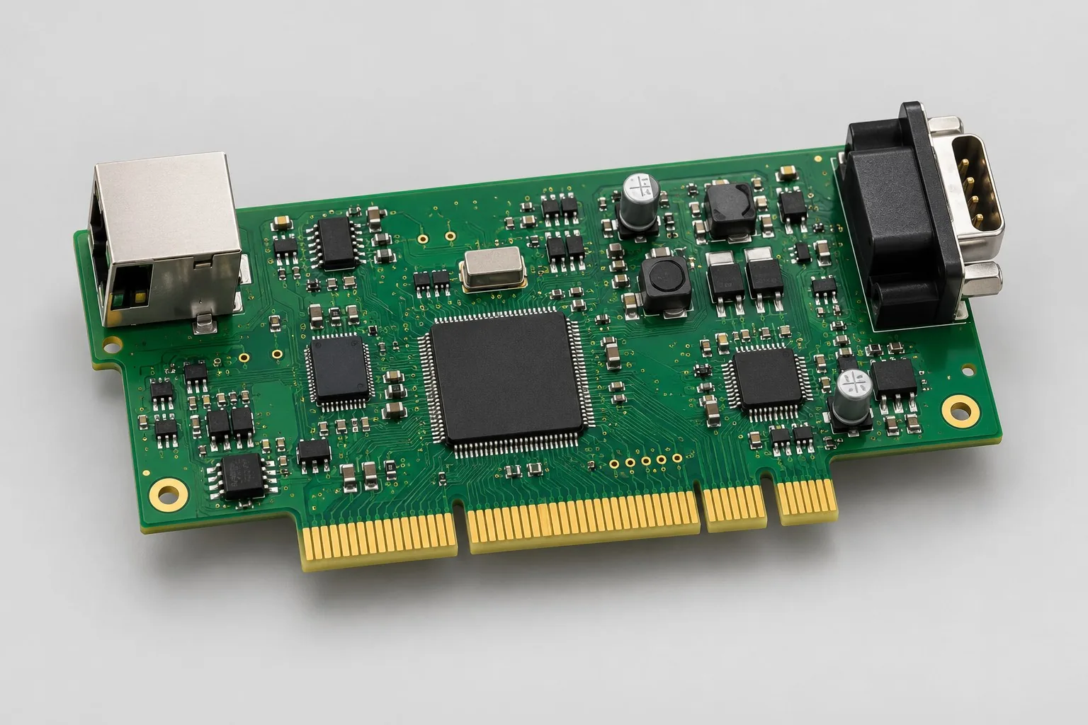
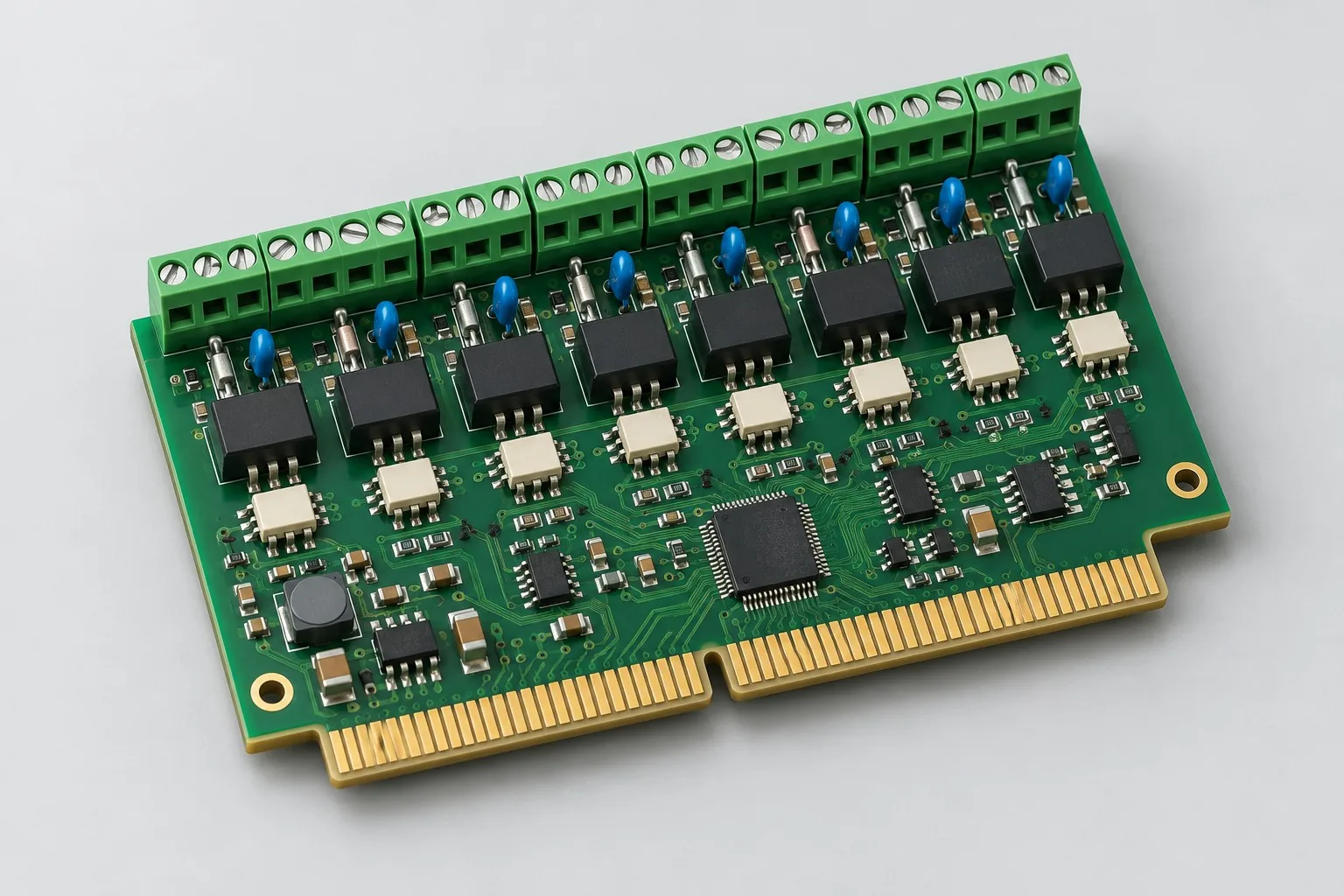
Industrial I/O gold-finger modules expand discrete inputs, analog inputs, and low-side DC outputs on host backplanes. A local MCU handles I/O/diagnostics through SPI or RS485; freeze pinouts, thickness, contact regions, and power-off insertion/removal together.
Custom development reference design. The parameters below are requirement configurations and design targets; validate product performance through agreed prototype tests.
| Functional Partition | Design and verification scope |
|---|---|
| Field I/O Terminals | Define ranges/loads for 8 24V discrete inputs, 2 analog inputs, and 4 outputs individually; prevent field-terminal miswiring. |
| Isolation and Level Shifting | Select isolation, level shifting, and port protection for field ground-potential differences and inputs. |
| Interface logic / MCU | Local MCU handles I/O/diagnostics; freeze protocol and backplane timing for SPI/RS485. |
| Host Gold Fingers | Map power, ground, and signals to each gold finger; check thickness, bevels, and slot keying together. |
| Power supply / Ground pins | Convert 24V/5V backplane input to local 3.3V; check contact voltage drops, parallel-contact current sharing, and concurrent outputs. |
| Connector and Fault Status | Base version requires power-off insertion/removal; check contact resistance, latches, and fault states after repeated mating. Do not assume hot-swap support. |
How much does industrial IO expansion design cost, and how is it quoted?
Industrial I/O card costs include backplane adaptation beyond circuitry. Review gold-finger pinouts, contact currents, thickness/bevels, and locking structures; integrate field I/O with actual backplanes. Daughtercard layout differs from developing backplane protocols. Itemize backplane revisions, harnesses, and fixtures separately.
Quotation terms depend on the approved files, quantity, material supply, tests and delivery requirements.
Prepare a structured RFQ or use the short inquiry form.
| Quotation Items | What services are included | What to Check When Comparing Quotes |
|---|---|---|
| Circuit and PCB Design | Backplane pinout and gold finger mechanical fit | Reusable portions of existing designs and circuit/mechanical changes |
| Software and Validation | Field I/O, contact, and concurrent-operation tests | Daughtercards/backplanes are separate circuit objects; existing backplanes require slot/pinout documentation and agreed compatibility tests |
| Prototype Preparation | Bare PCB, BOM procurement, assembly, and agreed prototype quantity | Whether material/component revisions, prototype quantities, and test targets match |
| Subsequent Revision | Record new requirements separately from post-test corrections | How agreed changes, source files, and validation results are delivered |
How should gold-finger I/O cards and terminal-connected control boards be selected?
Compare plug-in cards for frequently replaced backplane modules and terminal boards for fixed wiring. Cards require pinouts, thickness, bevels, and current distribution, with actual-backplane integration costs included.
Can industrial I/O cards be hot-swapped?
The base approach requires power-off insertion/removal. Live replacement adds power sequencing, current limiting, signal states, and software recovery. Gold fingers alone do not establish hot-swap support.
Do I/O expansion design fees include backplane design?
Daughtercards/backplanes are separate circuits. Existing backplanes require slot/pinout documentation and agreed compatibility tests. New backplanes, harnesses, and fixtures are separately itemized, not included by default.
Reference configuration for field I/O to host backplanes
| Configuration Field | Reference Configurations/Selections | Basis and Status |
|---|---|---|
| Finished Product Function | Card-slot I/O expansion | Design Objective |
| Input Reference | 8 24V discrete inputs + 2 analog inputs | Design Objective |
| Output Reference | 4 low-side DC outputs; load-defined rated current | Design Objective |
| Edge Board Interface | Gold-finger slot; backplane-defined pin count/pinout | Design Objective |
| Communication Configuration | Choose SPI/RS485 onboard backplane link | Design Objective |
| Operating Power Supply | Backplane 24V/5V input → local 3.3V | Design Objective |
| Main Controller Configuration | Small MCU for I/O management/diagnostics | Design Objective |
| Stackup Candidate | 4 layer FR-4, through-hole connection | Design Objective |
| Contact Process | Hard-gold candidate; thickness/bevels per connector requirements | Design Objective |
| Insertion Method | Power-off insertion/removal base version; no hot-swap claim | Design Objective |
| Mechanical Positioning | Coordinate slot, latch, thickness, and bevel design | Design Objective |
| Test Delivery | Contact mapping, I/O fixtures, and contact-resistance records | Design Objective |
Gold finger pinout and power-off insertion/removal
Define power, ground, and signal pinout for the board-edge interface first; distribute total contact current across enough parallel pins.
Local MCUs separate backplane protocols from field timing, aiding diagnostics; MCU-free versions use direct backplane control.
Separate analog measurements from discrete outputs to prevent high-current switching from adding measurement errors.
Design budget and trade-off examples
Check design targets with engineering calculations
If a supply contact carries design current 0.5A with assumed contact resistance 20mΩ, dissipation is I²R=5mW.
Conditions and Scope of Application:Contact resistance/current depend on selected connector conditions and do not establish mating lifetime; temperature rise, parallel-current sharing, and mechanics also require checks.
Replace examples with selected components and record margins; calculations support design choices, while prototype records support acceptance.
Power and layout for field I/O to host backplanes
- Separately identify gold-finger copper keep-outs, bevels, and connector envelopes; pads must avoid bevel-damage regions.
- Keep power-finger-to-protection paths short with current margin; place critical grounds near clock/signal returns.
- Place field-terminal protection near board edges; separate analog inputs from output drivers.
I/O card development input
- Backplane slot part numbers, thickness tolerances, and gold-finger pinouts
- Per-channel field ranges, actuator currents, and isolation requirements
- Mating frequency, mechanical locks, and maintenance rules
If circuit files exist, provide editable schematics, PCB, BOM, and current issues, and agree on review or revision scope. If only functions are defined, freeze this page's inputs before selection and circuit development. Agree separately on control-software and external-application responsibilities, interfaces, and acceptance.
I/O card phase delivery
| Stage | Engineering Work for This Proposal | Reviewable Deliverables |
|---|---|---|
| Requirements and Design Freeze | Freeze slots, pinouts, per-channel I/O, isolation, and maintenance insertion/removal rules | Functional/interface requirements, mechanical revision, acceptance conditions, and open items |
| Schematic and Component Selection | Design input conditioning, output drivers, MCU/backplane interfaces, and local supplies | Editable schematics, controlled BOM, footprint checks, and design calculations for these circuits |
| Layout and Routing | Define gold-finger contact/bevel keep-outs; separate analog sampling from output-current loops | PCB source files, actual stackup/hole/net constraints, DRC, and assembly-dimension checks |
| Simulation/Calculation | Calculate contact sharing/voltage drop; compare connector tolerances and concurrent-output measurement interference | Design calculations/models, input conditions, margins, and items awaiting measurement |
| Prototype and Software | Build I/O card prototypes; integrate backplane protocols, channel mappings, and diagnostics | Manufacturing package, I/O prototypes, controlled pinouts, agreed firmware, channel diagnostics, and backplane wiring instructions |
| Testing and Version Closure | Check per-pin connections, concurrent I/O, and protection on actual backplanes; complete approved mating comparisons | Procedures, wiring, raw results, and decisions for the prototype revision; include issue/change and limitation lists |
Mixed I/O and connector verification
- Per-pin continuity/short checks between gold fingers and backplanes
- Analog-measurement interference during simultaneous output switching
- Contact-resistance and mechanical checks after repeated mating
- Miswired inputs, output shorts, and backplane voltage drops
Check per-pin connections, concurrent I/O, and protection on actual backplanes; complete approved mating comparisons. Reports specify equipment, conditions, revisions, and criteria, recording passed and uncovered items.
Mixed I/O and connector validation worksheet
The table converts field I/O-to-backplane operation into executable checks. Freeze samples, equipment, environments, and allowable deviations before execution; link results to this revision's raw records.
| Verification Object | Pre-Production Freeze | How to Test Prototypes in Practice | Delivery and Acceptance Records |
|---|---|---|---|
| Pinout and Powering | Backplane slots, pin definitions, per-pin currents, and insertion/removal strategy | Check contact-face orientation pin by pin; measure startup and parallel-contact sharing | Deliver pinout/connector drawings and voltage-drop records; similar appearance does not establish compatibility |
| Mixed I/O | Input ranges, output loads, and allowable measurement error | Hold analog inputs constant while switching each discrete output | Retain coupling errors, contact/ground voltage drops, and protection responses; distinguish single-channel/concurrent states |
| Mechanical Contact | Plating, bevels, mating cycles, and acceptance methods | Inspect appearance and measure contact resistance under approved mating plans | Record samples/cycles/locations; gold thickness alone does not establish mating lifetime |
Manufacturing and assembly coordination for this design
- Include selective hard-gold areas, bevel angles, and solder-contamination keep-outs in fabrication drawings.
- Slot fixtures affect contact wear; count prototype and production testing separately.
Link design revisions to schematics, BOM, PCB, fabrication, and software documentation. When fabricators adjust stackup, materials, or holes, or Assembly parties propose substitutions, recheck critical electrical and test conditions together.
Common questions on purchasing and customization
How much does industrial IO expansion design cost, and how is it quoted?
A project-specific quotation requires review of the available files, quantity, materials, requested tests, delivery destination, taxes, shipping, and trade terms. Complete development separately prices circuits, firmware, prototypes, and verification. Any formula on this page organizes cost inputs; it is not a quoted rate.View cost items, calculation conditions, and sources.
How should I/O prototype card pinouts be checked?
Check power, ground, and signals pin by pin on actual backplanes; verify keying/channel mappings before concurrent I/O tests.
Can gold-finger daughtercard thickness be changed independently?
Thickness affects slot contact and locking. Check connector documentation/mechanical tolerances before changing it, then update fabrication files.
How should plug-in I/O budgets separate daughtercards and backplanes?
Itemize daughtercards with 8 24V inputs, 2 analog inputs, and 4 low-side outputs; backplanes cover power, slots, and SPI/RS485. Existing backplanes require adaptation and actual-board integration. Itemize new backplanes, fixtures, and locks separately; gold-finger fabrication costs are not complete card-development fees.
What must be frozen before I/O card Layout-only work?
Freeze gold-finger pinouts, thickness/bevels, contact currents, and slots; provide channel conditioning/driver circuits. Layout implements four-layer boards under backplane-return/port constraints. Routing before pinouts freeze risks revisions throughout interfaces, beyond edge-copper shapes.
What software costs arise when backplane links change from SPI to RS485?
Define addresses, I/O mappings, scan intervals, CRC/error handling, and disconnected output states; confirm transceivers/protection first. Assess existing I/O logic reuse, but communication endpoints and actual-backplane concurrency require new regression tests, beyond interface-chip price differences.
What I/O daughtercard files support slot maintenance?
Agree per-pin mappings, gold-finger fabrication/mechanical dimensions, contact/thickness conditions, and rated-load selection rationale for each channel. Deliver diagnostic codes/recovery strategies; retain actual-backplane, contact-resistance, and channel records to prevent appearance-based substitutions.
How should power-off cards be requoted for hot swapping?
Redesign power sequencing, inrush limiting, default signals, and software recognition/recovery; check contact mating order. Power-off insertion records cannot validate hot swapping. Budget both backplane/daughtercard impacts instead of merely changing descriptions.
Can industrial I/O daughtercards be reused across manufacturers' backplanes?
Compare pinouts, thickness, power, protocols, and keying individually; the I/O card name does not establish compatibility. Some field conditioning/diagnostics may remain reusable. Reagree backplane interfaces and actual-system tests to prevent damage from different power pinouts.
How should quotation documentation be prepared for industrial IO expansion design?
Initially describe functions, applications, and files. Engineering quotations further confirm slot part numbers, thickness tolerances, gold-finger pinouts, channel ranges, actuator currents, isolation, mating frequency, locks, and maintenance rules. Provide editable schematics, PCB files, and BOMs for existing designs, or revisions/reproduction records for faulty prototypes. List gaps as review tasks to prevent differing assumptions.
How should industrial IO expansion prototype verification costs be compared by operating condition?
Fix prototype quantities, revisions, equipment, and criteria sources. Separately review pinouts/power: freeze slots, pins, currents, and insertion strategy; check contact orientation, startup, and parallel sharing. Mixed I/O: freeze ranges, loads, and errors; hold analog inputs while switching outputs. Mechanical contacts: freeze plating, bevels, cycles, and acceptance methods; inspect appearance/resistance under approved mating plans. Specify raw-data and issue-closure deliverables; one successful power-up is not complete verification.
Compare related designs and plan the next step
Removable communication interface card design solution
Return to gold-finger PCB design selection · Select solution by device function · Discuss your design requirements
Documentation Basis and Boundaries
Engineering reference | Gerber manufacturing data: layer functions, drilling, and attributes: Ucamco data used for Manufacturing Files representation and attributes do not establish connector lifetime, I/O device performance, or host compatibility.