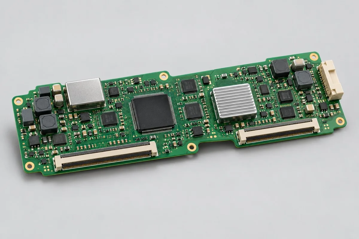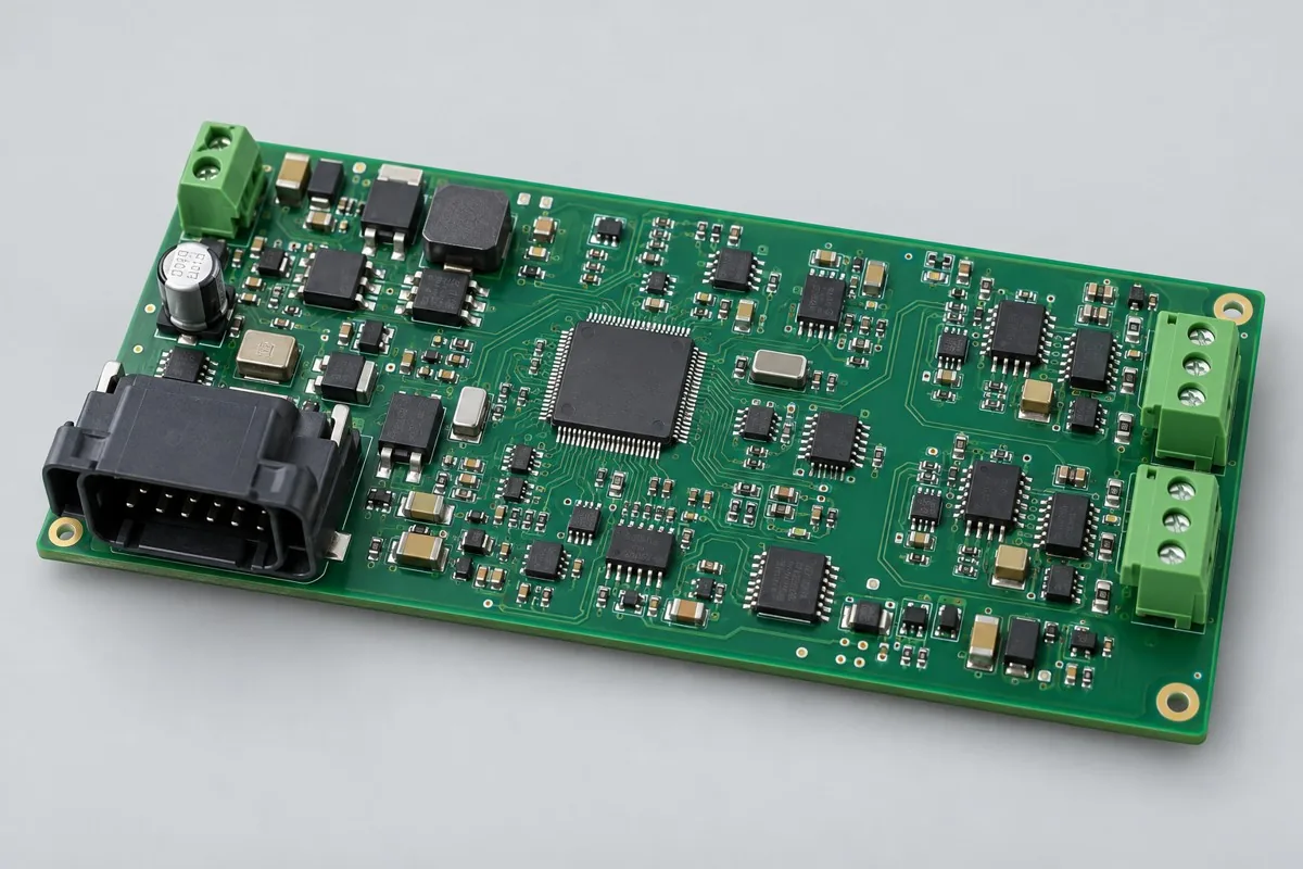
Engineering Reference Configuration
Automotive diagnostic PCB assembly: configuration, testing, and deliverables
The following adjustable engineering configurations support material, functional, and process review; they are not stocked models or commitments to current production-line capabilities. Approved fabrication documentation and order acceptance requirements govern.
Automotive diagnostic PCB assembly supports contract manufacturing and procurement review for vehicle-bus diagnostics, data buffering, and status reporting. First confirm MCU + CAN transceivers + memory, 2-CAN options, UART/USB maintenance and diagnostic sockets, and baseline 4-layer FR-4 separating interface protection and logic. Then compare SMT → socket secondary soldering → firmware/identity → bus testing scope and acceptance costs for bus frames, buffering, power-loss retention, and fault recovery. This page distinguishes control board + identity + protocol/event test logs from reference acquisition/diagnostic use, without vehicle control by default, helping assess whether quotations cover actual use. RFQ information reference:BOM · bare board · material supply
Reference specification and configuration options
| Options | Reference Configuration |
|---|---|
| Power and Logic Domains | 12V design input; automotive protection by project |
| Functional Module | Vehicle-bus diagnostics, data buffering, and status reporting |
| Core Components/Architecture | MCU + CAN transceivers + memory |
| Interface and Channels | 2-CAN options; UART/USB maintenance; diagnostic sockets |
| Board Layers and Material Options | Baseline 4-layer FR-4; separate interface protection and logic regions |
| Component types | SMD MCU/transceivers, protection components, through-hole automotive sockets |
| Assembly Route | SMT → socket secondary soldering → firmware/identity → bus testing |
| Material Supply Scope | Locked grade-specific MCU/transceiver and socket part numbers |
| Firmware and Parameters | Protocol stack, filtering rules, diagnostic identity, and upgrade revisions |
| Test Focus | Bus frames, buffering, power-loss retention, fault recovery |
| Deliverables | Control board + identity + protocol/event test logs |
| Configuration Limits/Options | Reference acquisition/diagnostic use; vehicle control not included by default |
How much does automotive diagnostic PCB assembly cost, and what does the quotation include?
CAN transceivers, protection components, memory, and automotive sockets determine material differences; itemize identity programming, dual-bus messages, buffering, and fault-recovery tests. Protocol development, vehicle adaptation, and licensed tools differ from ordinary board assembly; diagnostic socket shape cannot estimate complete diagnostic-equipment prices.
Quotation terms depend on the approved files, quantity, material supply, tests and delivery requirements.
Prepare a structured RFQ or use the short inquiry form.
| Cost Item | Scope for This Configuration | Billing frequency and work scope | Procurement Verification |
|---|---|---|---|
| Bare PCB and core components | MCU + CAN transceivers + memory; baseline 4-layer FR-4; separate interface protection and logic regions | Price according to actual bare-board/component purchase quantities; authorize critical components and substitutions individually | Locked grade-specific MCU/transceiver and socket part numbers |
| Placement and Post-Assembly | SMT → socket secondary soldering → firmware/identity → bus testing | Feeder/program setup per lot; assembly priced per board, joint, or process as agreed, with counting rules specified | SMD MCU/transceivers, protection components, through-hole automotive sockets |
| Manufacturing Preparation | Review stencils, first articles, and support tooling against the actual assembly route | New stencils/carriers may be separate one-time charges; verify panelization, revision, and condition before reuse | Reduced quantities do not automatically eliminate first-article or feeder setup |
| Functional Support | Bus frames, buffering, power-loss retention, fault recovery | Itemize test-method/fixture/script setup; agree execution charges per board, channel, or test duration | Separate supporting development from execution records for each board |
| Software and Parameters | Protocol stack, filtering rules, diagnostic identity, and upgrade revisions | When firmware exists, distinguish file programming/verification from software development; omit programming without a firmware revision | Customer-approved files, parameters, and readback rules determine scope |
| Delivery and Change | Control board + identity + protocol/event test logs; reference acquisition/diagnostic use, without vehicle control by default | Price accessories, retesting, and revision changes by approved work items; do not prefill fixed rates | Check BOM, tooling, programs, and acceptance revisions before reorders |
How do automotive diagnostic boards differ from general CAN interface boards?
General boards validate interface communication; diagnostic boards also involve authorized diagnostic protocols, filtering, identity, and event records. Vehicle diagnostics require software and data permissions as well as CAN connectivity; connectivity alone does not establish full diagnostic capability.
| Comparison Metric | Current Conditions | Factors Influencing Procurement Decision |
|---|---|---|
| Manufacturing Delivery | SMT → socket secondary soldering → firmware/identity → bus testing | Produce boards/assemblies per BOM and assembly drawings; this does not establish that every system function passes |
| Functional Acceptance | Bus frames, buffering, power-loss retention, fault recovery | Compare unit prices after defining test stimuli, limits, accessories, and records; review missing test inputs first |
| Configuration Options | 2-CAN options; UART/USB maintenance; diagnostic sockets; baseline 4-layer FR-4; separate interface protection and logic regions | Confirm circuit/program compatibility before reviewing assembly and test costs for interface, stackup, or component changes |
| Delivery Scope | Reference acquisition/diagnostic use; vehicle control not included by default | Complete-system accessories, application development, and project verification are not automatically included in board assembly |
How should single-CAN and dual-CAN diagnostic boards be selected?
Determine whether two channels are needed from actual vehicle networks and acquisition tasks, defining protocols, frame rates, filtering, and buffering too. Offline buffering adds memory and power-loss management; select capacity using record formats rather than Flash size alone.
- First list the vehicle-bus diagnostics, data buffering, and status reporting needed, distinguishing build-to-print manufacturing, configuration changes, and new-function development.
- Then freeze complete part numbers for MCU + CAN transceivers + memory, 2-CAN options, UART/USB maintenance, diagnostic sockets, and baseline 4-layer FR-4 separating interface protection and logic. Separate consigned and sourced materials using locked grade-specific MCU/transceiver and socket part numbers.
- Use first articles to check SMT → socket secondary soldering → firmware/identity → bus testing and protocol stack, filtering rules, diagnostic identity, and upgrade revisions. If only program files are supplied, agree on programming verification first; review development separately.
- Turn bus frames, buffering, power-loss retention, and fault recovery into acceptance items with stimuli, limits, and records, specifying fixture ownership, per-board execution, and post-rework retests.
- Finally confirm control board + identity + protocol/event test logs and reference acquisition/diagnostic use, without vehicle control by default. Compare total prices at equal quantities, accessories, and test scope, and freeze order revisions.
Applicable uses and situations requiring separate review
Authorized automotive diagnostics, vehicle-event recording.
Unauthorized active vehicle control, safety functions such as braking/steering, or treating diagnostic reference boards as qualified production automotive ECUs are outside this page's default scope. Wireless T-BOX requirements also add communication, antennas, and system configuration.
Assembly Challenges for This Product
Inspect automotive socket mechanical and signal pins separately; define protection-component orientation and CAN termination by network position. Check program behavior when buffer writing coincides with power loss; do not connect simulated-bus test messages to unapproved actual vehicles.
Structural, thermal, and configuration trade-offs
More buffering reduces offline data-loss risks but increases power-loss write/recovery and data-maintenance costs. Select isolated/non-isolated dual buses by vehicle-network architecture; more processing power cannot solve undefined bus protocols.
Product-specific test matrix
| Test stage | Inspection/Functional Methods | Acceptance Record |
|---|---|---|
| Port Message | Transmit/receive message sets on each CAN port, checking errors and load | Frame count/error/port mapping |
| Data Retention | Simulate power loss and reboot after write | Record integrity and time/sequence continuity |
| Exception and Permissions | Bus disconnection, upgrade failure, and authorized-operation tests | Recovery behavior and program version |
Defect Handling and Acceptance
Diagnose reversed transceivers, incorrect termination types, address/identity errors, and corrupted buffers separately. Acceptance uses specified protocol message sets; CAN loopback alone cannot establish compatibility with every vehicle model.
Automotive CAN diagnostic PCB assembly: material supply and revision control
Check CAN transceiver common-mode ranges, protection, and operating conditions; memory substitutions also require software and power-loss validation. Customers provide authorized message sets and identity assignments; general sourcing does not define vehicle-interface responsibilities.
Prototyping vs. Production Differences
Use simulated buses and readable logs during prototypes; freeze protocol revisions and identities in production, retaining port results and shipping-firmware checksums in fixtures. List vehicle-level validation and regulatory scope separately in contracts.
Delivery Configuration
Control board + identity + protocol/event test logs. Reference acquisition/diagnostic use; vehicle control not included by default.
Convert this configuration into a reviewable order
For automotive diagnostic communication control board orders, check BOM, quantity, material supply, and conditions below; add pick-and-place files/CPL, DNP items, and assembly drawings for SMT. For programming, provide files, programming rules, and checksums corresponding to protocol stack, filtering rules, diagnostic identity, and upgrade revisions. Review costs separately for materials, SMT → socket secondary soldering → firmware/identity → bus testing, and required stencils/line setup, support carriers, and test equipment. Reapprove revisions after documentation changes; agree on delivery milestones after kit completion and scheduling confirmation.
| Required project inputs | Engineering Decisions Affected | Records/delivery as agreed in the order |
|---|---|---|
| Diagnostic Protocols and Buses | Specify CAN versions, rates, diagnostic messages, and termination settings to determine bus simulators and test scripts. | Retain messages, error counts, and recovery logs; correct CAN transmission/reception does not establish every diagnostic function passed. |
| Automotive Software Identity | Provide firmware, calibration, and device-identification programming rules. | Link board IDs to software checksums and identification results; contract assembly does not replace vehicle authorization/certification. |
Automotive diagnostic PCB assembly FAQ
How much does automotive diagnostic PCB assembly cost, and what does the quotation include?
For standard placement, first calculate board quantity × billable points per board × price per point + setup fee. A project-specific quotation requires review of the available files, quantity, materials, requested tests, delivery destination, taxes, shipping, and trade terms. This is a placement-only reference; bare PCBs, materials, and testing are charged separately. Any formula on this page organizes cost inputs; it is not a quoted rate.View cost items, calculation conditions, and sources.
How do automotive diagnostic boards differ from general CAN interface boards?
General boards validate interface communication; diagnostic boards also involve authorized diagnostic protocols, filtering, identity, and event records. Vehicle diagnostics require software and data permissions as well as CAN connectivity; connectivity alone does not establish full diagnostic capability.
How should single-CAN and dual-CAN diagnostic boards be selected?
Determine whether two channels are needed from actual vehicle networks and acquisition tasks, defining protocols, frame rates, filtering, and buffering too. Offline buffering adds memory and power-loss management; select capacity using record formats rather than Flash size alone.
Does automotive diagnostic PCB assembly include vehicle protocols?
Programming customer protocol software and developing new protocols are separate tasks. List message cases, identity assignments, and upgrade recovery explicitly; without authorized protocols and vehicle data, do not promise universal diagnostic results.
How should power-loss data be accepted on dual-CAN diagnostic boards?
Record specified messages and buffers first, then execute approved power-loss recovery cases and read back event/file integrity. Communication indicators alone cannot establish retained data or correct identity configuration.
Does offline buffering only add memory-component costs to diagnostic boards?
Buffering also involves filtering, data formats, and recovery of writes interrupted by power loss; test duration and software work may change. Align recording tasks and power-loss results in cost comparisons rather than memory capacity alone.
Can a consigned diagnostic socket be replaced with the same shape?
Check pinouts, mechanical fastening, and complete part numbers; equal shapes do not establish identical vehicle-interface definitions. Quotations also need harnesses and authorized protocols; socket assembly alone cannot establish diagnostic adaptation.
How should port-message testing be included in automotive diagnostic PCB assembly procurement acceptance?
The reference method transmits/receives message sets on each CAN port, checking errors and load; records include frame counts/errors/port mapping. Provide test inputs, applicable configurations, and acceptance limits first, then agree on first-article validation and per-board execution scope. Price test preparation separately from each execution. Without limits, review methods first rather than labeling completed operations as specification compliance.
How should data-retention testing be included in automotive diagnostic PCB assembly procurement acceptance?
The reference method writes data, then simulates power loss and restart; records include record integrity and time/sequence continuity. Provide test inputs, applicable configurations, and acceptance limits first, then agree on first-article validation and per-board execution scope. Price test preparation separately from each execution. Without limits, review methods first rather than labeling completed operations as specification compliance.
How should fault/permission testing be included in automotive diagnostic PCB assembly procurement acceptance?
The reference method tests bus disconnection, upgrade failures, and authorized operations; records include recovery behavior and software revisions. Provide test inputs, applicable configurations, and acceptance limits first, then agree on first-article validation and per-board execution scope. Price test preparation separately from each execution. Without limits, review methods first rather than labeling completed operations as specification compliance.
How should identity and buffering tests be priced when diagnostic boards switch from test to production firmware?
List checksums, filtering rules, diagnostic identities, and upgrade revisions for test software and production protocol software separately. After production programming, verify identity and retest approved CAN messages, buffer records, and power-loss recovery cases. If authorized operations or message sets change, itemize script changes and per-board execution. Test-software communication does not establish production diagnostic functions or vehicle authorization passed.
Must first-article, stencil, and line-setup charges be recalculated for repeat automotive diagnostic PCB assembly orders?
The route is SMT → socket secondary soldering → firmware/identity → bus testing. For SMT, check stencils and panels; for through-hole or later installation, check support and assembly methods. Agree on setup and first articles for this batch; reuse old tooling only when revision, location, and condition match. After changing SMD MCU/transceivers, protection components, through-hole automotive sockets, or interfaces, review tooling effects and bus frames, buffering, power-loss retention, and fault recovery before confirming recurring charges.
How should total automotive diagnostic PCB assembly prices be compared when critical components are consigned and others sourced?
Build a procurement responsibility table using locked grade-specific MCU/transceiver and socket part numbers. Confirm complete part numbers, quantity, packaging, and excess-material rules with materials. Consignment only changes procurement boundaries; SMT → socket secondary soldering → firmware/identity → bus testing and bus frames, buffering, power-loss retention, and fault recovery remain actual work. Approve shortage, substitution, or batch-change impacts first; consigned-material unit prices cannot be compared directly with material-inclusive assembly totals.
Which items need retesting after automotive diagnostic PCB assembly rework or supplemental orders?
Select retests by change impact. Original acceptance covers bus frames, buffering, power-loss retention, and fault recovery; shipping records comprise control board + identity + protocol/event test logs. If repairs affect power, interfaces, critical analog circuits, or software revisions, check related tests rather than repaired joints alone. Align supplemental orders with original BOM, parameters, and test equipment. Agree on retest costs by approved items and actual quantity, without assuming free service or fixed turnaround.
Compare Other Products in This Category
- Automotive central control display interface board: Display and touch, backlight and sleep.
Return to automotive electronics PCB assembly configuration comparison · Component Supply and Procurement · Testing and Delivery Scope
Material and Process Reference
- Engineering reference | SMT packages and assembly methods: pads, stencils, and thermal processes: a package/assembly method index only; not evidence that the product configurations on this page are models produced by KFPCBA