Engineering Selection Reference
Six-layer BMS PCB engineering reference and review boundary
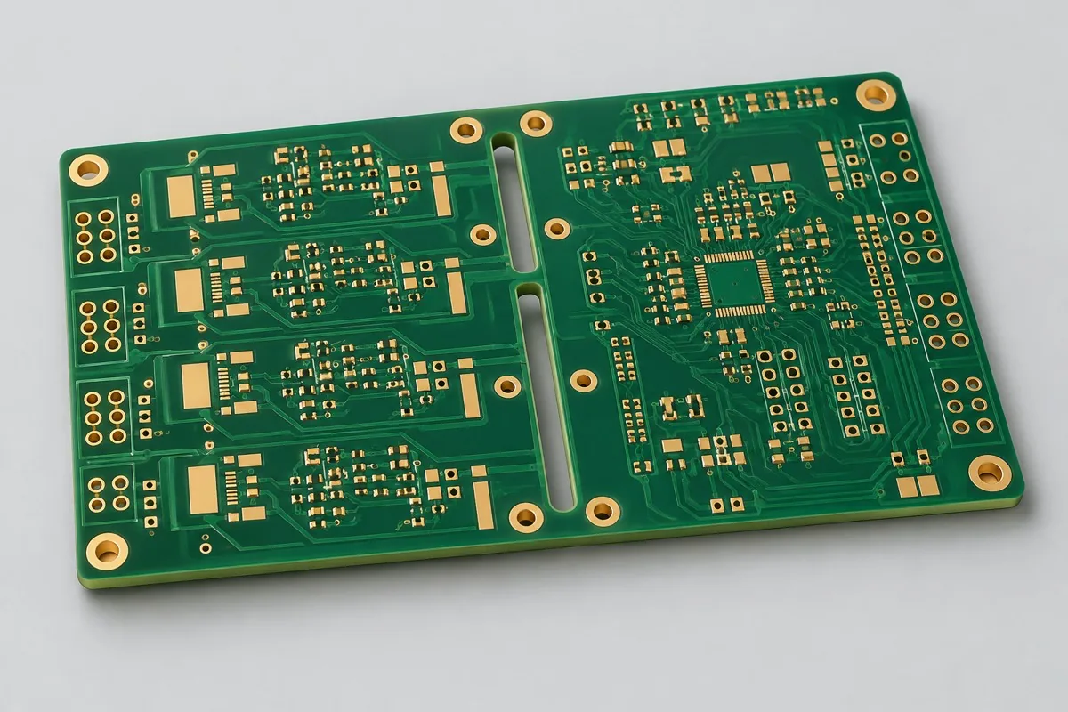
This page presents an illustrative six-layer through-hole BMS configuration for organizing a bare-board fabrication review. It does not document a KFPCBA production lot. Layer count, TG170 designation and all other construction inputs remain unverified until approved project data is available.
Known record and open inputs
| Item | Illustrative reference input | Required for a new project |
|---|---|---|
| Application context | BMS sensing and control board reference | Voltage domains, sensing topology, balancing-current paths, isolation rules, and installation environment |
| Construction | Six-layer through-hole configuration | Released stackup, dielectric thicknesses, copper by layer, finished thickness, and material part numbers |
| Holes and features | Hole table not supplied for this reference | Drill files, finished-hole groups, slots, plated/non-plated definitions, tolerances, and any press-fit or filled-via requirements |
| Acceptance | No attributable production lot record | Electrical-test data, dimensional and visual criteria, coupon or microsection requirements, sampling, reports, and traceability |
Fabrication data required for a new review
- Gerber or ODB++ data, NC drill files, board outline, fabrication drawing, and revision identity
- Approved stackup and material list, including copper weight for every layer and permitted substitutions
- Controlled-impedance groups, creepage/clearance constraints, sensing-net keepouts, and current-carrying regions
- Panelization, quantity, target date, surface finish, marking, cleanliness, packaging, and delivery destination
- Electrical test, coupon, microsection, dimensional, visual, and documentation requirements
Review sensing, power, isolation, and hole structures separately
A BMS label does not determine copper weight or layer count. Sensing paths prioritize leakage control, reference continuity, noise coupling, and traceable net definitions. Balancing and power paths require their own current, temperature-rise, copper-area, and connection review. Isolation regions must be defined from the product requirements rather than inferred from a photograph or category name.
The fabricator reviews manufacturability against the released data. Component selection, firmware, calibration, complete-system safety, and sensing accuracy remain separate responsibilities unless they are explicitly included in the project scope.
Delivery and acceptance records
The controlled quotation should state the board revision, quantity unit, panel or individual-board delivery basis, material and finish requirements, inspection scope, included reports, tooling ownership, packaging, freight, taxes, and quote validity. Prototype release should retain agreed deviations and test results so a repeat order can be compared against the same controlled revision.
For a comparable quotation, use variables rather than an unsupported public rate: Q_project = Q_fabrication + Q_tooling + Q_inspection + Q_logistics. Each quotation must define what is included in those variables; assembly, components, programming, and complete-system verification are excluded unless separately listed.
Next step for this BMS PCB configuration
Use the engineering RFQ when fabrication files are available. If the stackup, material list, or acceptance plan is incomplete, start with the short project inquiry and identify the open items. Compare the adjacent twelve-layer high-Tg reference only by its own released construction; do not transfer its parameters to this board.
Source and verification boundary
This page is an engineering reference, not evidence of a delivered KFPCBA board. Material designations, copper distribution, process feasibility, schedule, certification scope and lot results require controlled project evidence and responsible-party approval before use as commitments.