Engineering reference design · prototype validation pending
Power-divider board design: passive one-input/two-output feeds
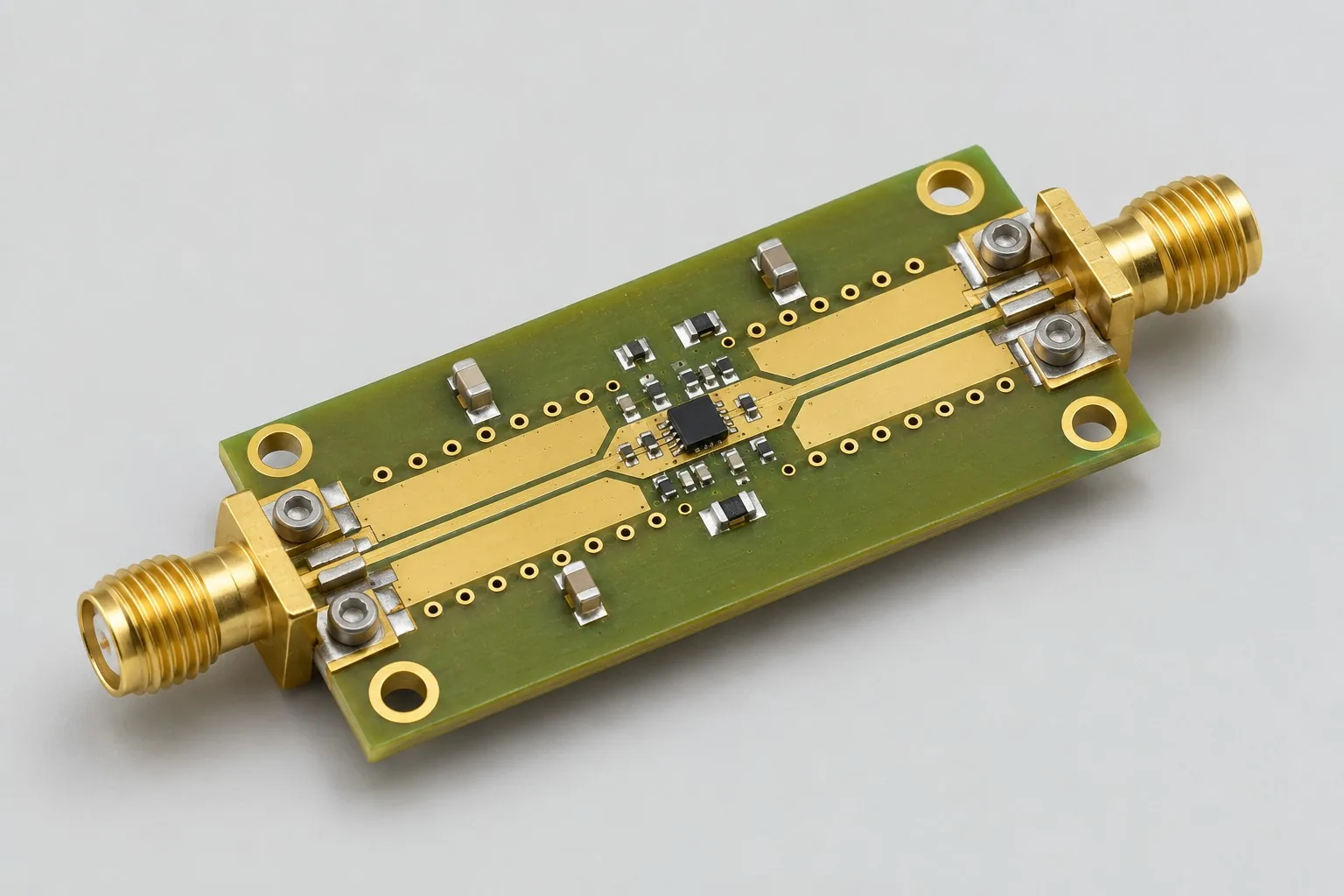
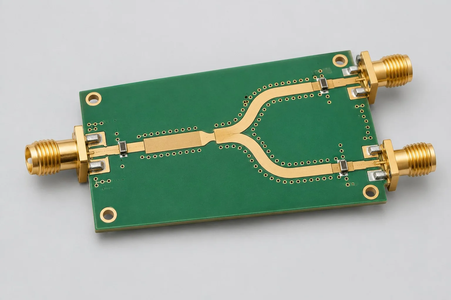
2.4GHz power-divider boards split one RF input equally into two antenna feeds using Wilkinson or integrated dividers. Develop passive boards around three-port matching, isolation, and output amplitude/phase differences; include feedlines and actual antennas in separate system verification.
Custom development reference design. The parameters below are requirement configurations and design targets; validate product performance through agreed prototype tests.
| Functional Partition | Design and verification scope |
|---|---|
| RF Input Port | Define 2.4GHz bandwidth, input power, and connector reference planes; confirm source impedance. |
| Symmetric Power Distribution | Compare distributed Wilkinson and integrated dividers; select branch structures/isolation resistors by band and power. |
| Two-Channel Matched Transmission | Match branches by materials, electrical lengths, and port parasitics, beyond equal geometric lengths. |
| Dual Output Port | Include both output connectors/coaxial lengths in amplitude/phase budgets; agree load-mismatch ranges in advance. |
| Ground reference / via fence | Backside ground, via fences, and board edges jointly define transmission structures; passive base versions need no supply. |
| Amplitude and Phase Consistency | Measure three-port S-parameters, isolation, and amplitude/phase differences; check resistor temperature rise at target power, then separately report antenna coverage. |
How much does 2.4GHz power-divider board design cost, and how is it quoted?
2.4GHz divider development centers on three-port structures and amplitude/phase verification, beyond one-input/two-output counts. Wilkinson and integrated devices have different layout, material, and isolation conditions. Four-output expansion requires separate cascade/port review. Separate antenna-system testing from divider-network measurements.
Quotation terms depend on the approved files, quantity, material supply, tests and delivery requirements.
Prepare a structured RFQ or use the short inquiry form.
| Quotation Items | What services are included | What to Check When Comparing Quotes |
|---|---|---|
| Circuit and PCB Design | Three-port divider structures, electrical lengths, and isolation resistors | Reusable portions of existing designs and circuit/mechanical changes |
| Software and Validation | Phase difference and load mismatch test | Three-port S-parameters and antenna-array coverage are separate tasks |
| Prototype Preparation | Bare PCB, BOM procurement, assembly, and agreed prototype quantity | Whether material/component revisions, prototype quantities, and test targets match |
| Subsequent Revision | Record new requirements separately from post-test corrections | How agreed changes, source files, and validation results are delivered |
Should 2.4GHz dividers use Wilkinson or integrated devices?
Distributed structures support electrical-length studies but depend on board area/materials. Compare integrated-device size, bands, and power conditions. Evaluate devices, layout, ports, and verification together, beyond purchase prices.
Are equal-length traces sufficient for both divider outputs?
Compare complete electrical lengths, including connectors, coaxial cables, and transitions in amplitude/phase budgets. Equal geometric lengths may still produce port differences; measure both outputs' amplitude/phase and isolation at identical reference planes.
Do divider development quotations include antenna-coverage tests?
Three-port S-parameters assess divider networks; antenna-array coverage additionally depends on spacing and mounting. They are separate tasks, and quotations must identify each measurement object.
Reference configuration for passive one-input/two-output feeds
| Configuration Field | Reference Configurations/Selections | Basis and Status |
|---|---|---|
| Finished Product Function | 1 in 2 out passive antenna feed | Design Objective |
| Operating Band Target | 2.4GHz ISM requirement example | Design Objective |
| Input Output | 3 50 Ω RF ports | Design Objective |
| Power Divider Architecture | Choose Wilkinson or integrated power divider | Design Objective |
| Feeder Constraint | Match output electrical lengths, beyond geometric lengths | Design Objective |
| Material Candidate | Cost comparison of RF materials and low-loss FR-4 | Design Objective |
| Stackup Candidate | Two-layer RF board with a continuous backside ground plane | Design Objective |
| Power Supply Requirement | Passive basic version requires no power | Design Objective |
| Component Configuration | Isolation resistor or integrated divider; power-rating review | Design Objective |
| Connection Method | SMA/board-to-board RF connector options | Design Objective |
| Structural Reference | Arrange two output ports by antenna location | Design Objective |
| Validation outputs | Amplitude/phase imbalance, S-parameters, and antenna-system testing | Design Objective |
Wilkinson and integrated-divider approaches
Distributed microstrip supports electrical-length studies; integrated dividers save space but require band/power-rating checks.
Divider networks alone cannot guarantee array patterns; antenna spacing and phase targets must come from system requirements.
Include both output connector/coaxial lengths in overall phase budgets.
Design budget and trade-off examples
Check design targets with engineering calculations
With ideal equal division into two outputs, each receives half the input power: 10log10(1/2)≈−3.01dB; add actual insertion loss separately.
Conditions and Scope of Application:Distinguish splitting loss from additional dissipative loss; test matching, isolation, and amplitude/phase differences over target bands.
Replace examples with selected components and record margins; calculations support design choices, while prototype records support acceptance.
Power and layout for passive one-input/two-output feeds
- Arrange branches symmetrically with short isolation-resistor connections; avoid connector locations forcing long detours on one branch.
- Calculate electrical lengths from materials and target frequency, then assess corner, pad, and via parasitics.
- Maintain continuous backside ground; include nearby ground vias and board edges in electromagnetic analysis.
Power Divider Board R&D Inputs
- Antenna types, physical spacing, phase, and power-division targets
- Operating bandwidth, input power, and connector/coaxial documentation
- Outline constraints, material costs, and measurement fixtures
For existing circuits, provide editable schematics, PCB files, BOMs, and current issues, agreeing review/revision scope. For functional requirements alone, freeze this page's inputs before selection and circuit development. Define base-board ports, test wiring, and assembly scope; review added active/control circuits separately.
Power Divider Board Phase Deliverables
| Stage | Engineering Work for This Proposal | Reviewable Deliverables |
|---|---|---|
| Requirements and Design Freeze | Freeze antenna spacing, phase/equal-split targets, bandwidth, power, and outline | Functional/interface requirements, mechanical revision, acceptance conditions, and open items |
| Schematic and Component Selection | Design Wilkinson or component-based dividers; select connectors and isolation-resistor ratings | Editable schematics, controlled BOM, footprint checks, and design calculations for these circuits |
| Layout and Routing | Lay out symmetric electrical lengths, port transitions, and continuous ground; check trace-etch tolerances | PCB source files, actual stackup/hole/net constraints, DRC, and assembly-dimension checks |
| Simulation/Calculation | Analyze splitting/dissipative loss, three-port S-parameters, and load-mismatch thermal budgets | Design calculations/models, input conditions, margins, and items awaiting measurement |
| Prototype and Software | Fabricate passive divider samples; prepare calibration/wiring plans and actual antenna connections | Manufacturing package, passive divider samples, three-port drawings, test wiring/calibration configurations, Touchstone, and antenna-test records |
| Testing and Version Closure | Measure amplitude/phase balance and isolation, check mismatch temperature rise, and compare coverage under fixed deployment | Procedures, wiring, raw results, and decisions for the prototype revision; include issue/change and limitation lists |
Power divider amplitude/phase and port isolation verification
- Three-port S-parameters and port isolation measurement
- Amplitude/phase balance measurements across operating bandwidth
- Isolation resistor temperature rise under rated target input
- Directivity/coverage comparison with actual antennas
Measure amplitude/phase balance and isolation, check mismatch temperature rise, and compare coverage under fixed deployment. Reports specify equipment, conditions, revisions, and criteria, recording passed and uncovered items.
Divider amplitude/phase and port-isolation verification worksheet
The table converts passive one-input/two-output feeds into executable checks. Freeze samples, equipment, environments, and allowable deviations before execution; link results to this revision's raw records.
| Verification Object | Pre-Production Freeze | How to Test Prototypes in Practice | Delivery and Acceptance Records |
|---|---|---|---|
| Three-Port Balance | Bandwidth, divider topology, impedance, and amplitude/phase balance targets | Measure calibrated port S-parameters, isolation, and amplitude/phase differences | Deliver raw three-port files and acceptance tables, evaluating each frequency |
| Load Condition | Antenna impedance/standing-wave changes and target input power | Compare matched loads with approved mismatch conditions; measure isolation-resistor temperature rise | Retain load-reflection conditions and temperature rise; mismatch power is not matched-load rated power |
| System Coverage | Antenna model, spacing, feed line, and enclosure | Keep the RF source constant; compare single-antenna and divided-feed deployments | Deliver scenario diagrams and coverage data, separating divider insertion loss from antenna-placement effects |
Manufacturing and assembly coordination for this design
- Panelization optimization must not arbitrarily change critical electrical lengths or copper widths; record etch compensation.
- Maintain consistent mechanical positioning during output-port soldering; include calibration structures and coaxial-cable identifiers in reports.
Link design revisions to schematics, BOM, PCB, fabrication, and software documentation. When fabricators adjust stackup, materials, or holes, or Assembly parties propose substitutions, recheck critical electrical and test conditions together.
Common questions on purchasing and customization
How much does 2.4GHz power-divider board design cost, and how is it quoted?
A project-specific quotation requires review of the available files, quantity, materials, requested tests, delivery destination, taxes, shipping, and trade terms. Any formula on this page organizes cost inputs; it is not a quoted rate.View cost items, calculation conditions, and sources.
How should four-output divider expansion budgets be compared?
Add cascade networks and output ports, then reassess loss, isolation, electrical lengths, and power; do not simply double two-output board prices.
What load conditions are used for power divider board validation?
Fix port reference planes and loads; record matching, dual-output amplitude/phase, and temperature rise at target power, then separately report actual antenna-system performance.
How should distributed and integrated divider budgets be compared?
Freeze three ports, outline, and target band. Itemize electrical-length design/isolation resistors for distributed designs and component selection/port layout for integrated designs. Both include same-plane amplitude/phase, isolation, and load-mismatch tests. Then compare area/materials; one divider's price is not complete development cost.
What fixed structures are needed for Layout-only two-output dividers?
Provide Wilkinson geometry or integrated-device references, stackups, three-port models, antenna-end positions, and allowable amplitude/phase differences. Undefined geometry/materials require passive-structure design. Equal-length routing cannot replace electrical-length and port-phase budgets.
Why might passive-divider quotations include software?
A basic 1-input/2-output passive board needs no onboard firmware. Software items must identify analyzer-data processing, antenna-system testing, or external switching control. Confirm deliverables before purchase; passive networks and system-control development are separate tasks.
What interface documentation must designers deliver when customers measure two-output samples?
Freeze three-port models, reference planes, target bands, port terminations, and amplitude/phase/isolation criteria. Designers deliver models, manufacturing packages, port drawings, and calibration/connection methods; customer measurements provide raw three-port S-parameters linked to sample revisions. Separate data-analysis, sample-measurement, and antenna-coverage responsibilities; screenshots alone cannot close divider verification.
How is revision work priced when both output positions change?
Positions affect electrical lengths, transitions, isolation, and antenna spacing. List board geometry and connection changes before rechecking amplitude/phase. If external antennas also move, coverage testing adds a system object and should be quoted separately from divider-network regression.
Can 2.4GHz divider boards be reused directly at 5.8GHz?
Band changes alter distributed electrical lengths, isolation-resistor behavior, and device coverage. Assess retention of port mechanics, but redesign divider networks and material budgets. Shared 50Ω impedance or connectors do not establish dual-band compatibility.
How should quotation documentation be prepared for 2.4GHz divider design?
Initially describe functions, applications, and available files. Engineering quotations further confirm antenna types/spacing, phase/power-division targets, bandwidth, input power, connector/coaxial details, outline constraints, material costs, and fixtures. Provide editable schematics, PCB files, and BOMs for existing designs, or revisions/reproduction records for faulty prototypes. List gaps as review tasks to prevent differing assumptions.
How should 2.4GHz divider prototype verification costs be compared by operating condition?
Fix prototype quantities, revisions, equipment, and criteria sources. Separately review three-port balance: freeze bandwidth, topology, impedance, and balance targets, then measure calibrated S-parameters/isolation/amplitude/phase. Loads: freeze antenna impedance/standing-wave changes and target power; compare matched/approved mismatched loads and resistor temperature rise. Coverage: freeze antennas, spacing, feedlines, and enclosure; compare single-antenna/divided-feed deployment with identical RF sources. Specify raw-data and issue-closure deliverables; DC continuity alone does not verify the passive RF path.
Compare related designs and plan the next step
5.8GHz microwave channel evaluation board design
Return to high-frequency PCB design selection · Select solution by device function · Discuss your design requirements
Documentation Basis and Boundaries
Engineering reference | RO4350B material: high-frequency parameters and stackup confirmation: Material documentation supports dielectric/fabrication references only; verify Wilkinson structures, integrated dividers, and isolation resistors against actual designs and manuals.