Engineering reference design · prototype validation pending
Smart aquarium control board design: from water sensing to low-voltage pumps and lighting
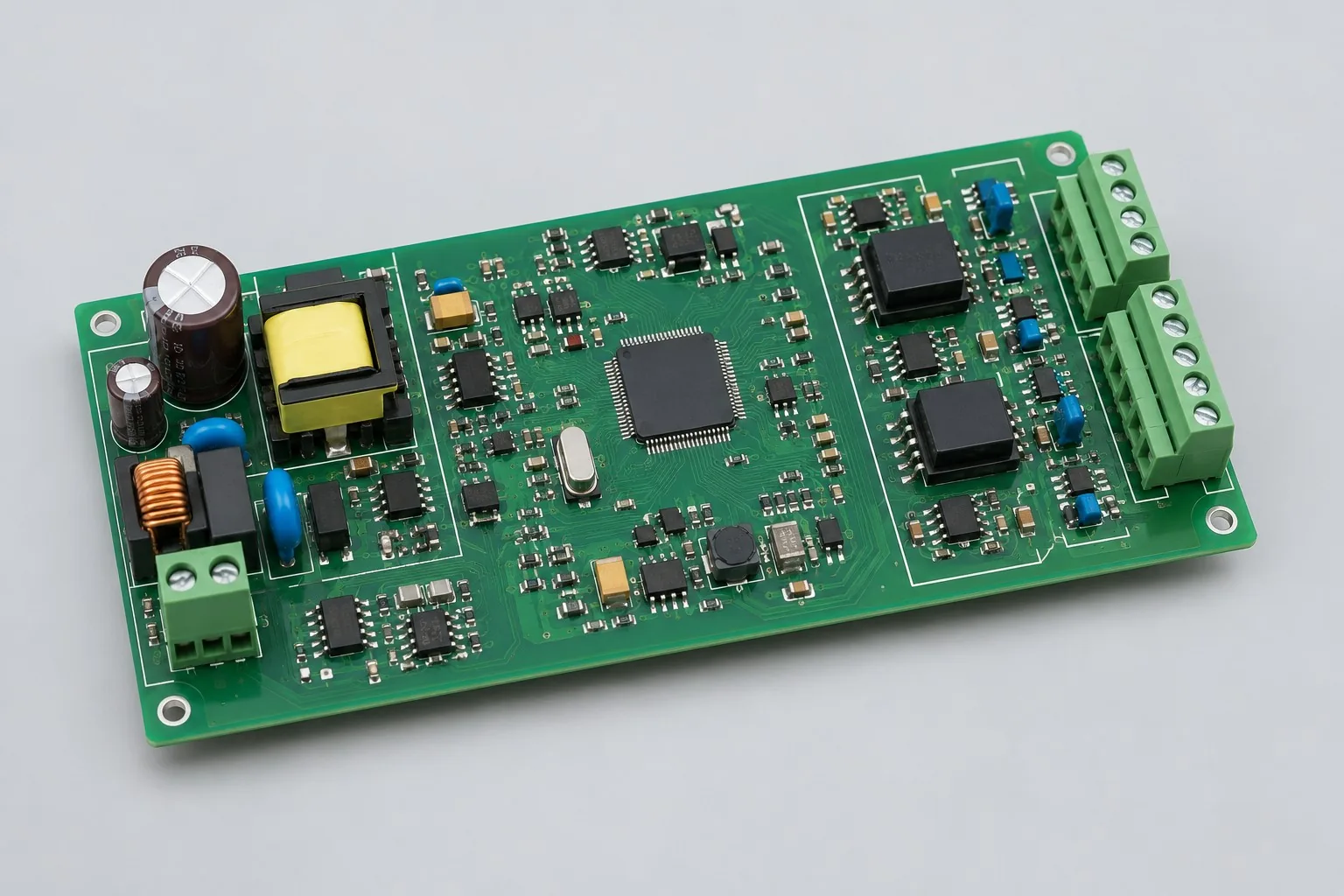
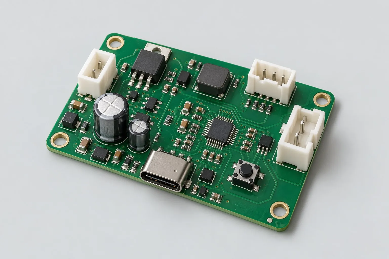
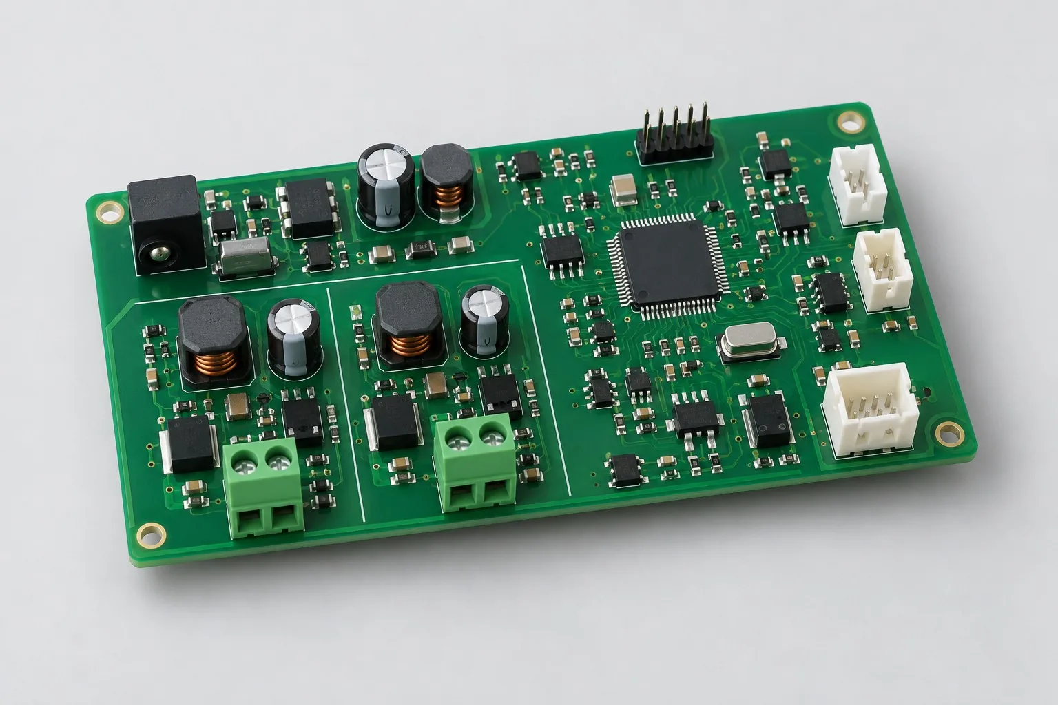
Smart aquarium control board design measures water temperature and level, schedules a 12V circulation pump and two LED dimming channels, and handles low water, disconnected probes, and lost time. The basic board connects only to low-voltage pumps and lighting; it provides only a control signal for a heater, with mains switching hardware reviewed separately.
Custom development reference design. The following parameters are requirement configurations and design targets; validate functions and performance through agreed prototype tests.
| Functional Partition | Design and Inspection Objects |
|---|---|
| Temperature / Water Level Sensing | Design temperature probe and level-switch connections and protection for their installed locations; distinguish fault readings from valid data. |
| Environment control state machine | The controller manages schedules, alarms, low-water shutdown, and RTC recovery; probe faults trigger the agreed safe state. |
| Low-Voltage Pump / LED Driver | Compare MOSFET and DRV8876-class drivers for the 12V pump; design lighting branches for the actual dimmable loads. |
| Water pump and lighting interface | Clearly identify pump/lighting ports and heater control signals to prevent misconnection; mains immersion heaters must not connect directly to the basic board. |
| Low-voltage power supply and protection | Budget the 12V adapter for pump startup, full lighting load, and control circuitry; separate input and sensing return paths. |
| Low Water / Sensor Fault | Inject low-water, open/short-circuit, RTC time-loss, and power-loss faults separately; record pump/lighting states and user alarms. |
How much does smart aquarium control board design cost, and how is it quoted?
Calculate aquarium board costs from the combination of pumps, lighting, sensing, and fault states. Scheduled pump/lighting control differs in scope from adding water level, temperature, and sensor-failure handling; mains heater control is also a separate item. Quote low-voltage hardware, local firmware, simultaneous testing with actual pumps and lighting, and added probes or application software separately.
Quotation terms depend on the approved files, quantity, material supply, tests and delivery requirements.
Prepare a structured RFQ or use the short inquiry form.
| Quotation Items | What services are included | What to Check When Comparing Quotes |
|---|---|---|
| Circuit and PCB Design | Water temperature and level sensing, concurrent low-voltage pump/lighting operation, and power supply | Reusable portions of existing designs and circuit/mechanical changes |
| Software and Validation | Failure state and device recovery test | Water temperature, level, and low-voltage pump/lighting control do not constitute water-quality analysis |
| Prototype Preparation | Bare PCB, BOM procurement, assembly, and agreed prototype quantity | Whether material/component revisions, prototype quantities, and test targets match |
| Subsequent Revision | Record new requirements separately from post-test corrections | How agreed changes, source files, and validation results are delivered |
How does an aquarium control board differ from a pet water fountain control board?
An aquarium coordinates pumps, lighting, and environmental monitoring, while a water fountain focuses on water level and its drinking-water pump. Loads, operating cycles, and failure states differ, so boards cannot be reused directly merely because both use pumps.
Can an aquarium control board directly control a mains immersion heater?
The low-voltage approach on this page does not establish mains switching capability. For heater control, define the interface, insulation, and failure states separately, with scope determined by the complete product's requirements. Adding a relay alone does not complete this work.
Does the aquarium control board development fee include water-quality analysis?
Water temperature, level, and low-voltage pump/lighting control do not constitute water-quality analysis. Specify functions and tests for additional probes, calibration, or mobile apps. The quotation should also cover supply and temperature-rise verification with pumps and lighting running together.
Reference configuration for water sensing and low-voltage pump/lighting control
| Configuration Field | Reference Configurations/Selections | Basis and Status |
|---|---|---|
| R&D Direction | Low-voltage aquarium pump, lighting, and sensing design reference | Illustrative design direction; requirements and prototype validation must be agreed |
| Reference Function | Water temperature/level monitoring, circulation pump, and lighting control | Design Objective |
| Power Supply Objective | Example requirement for a 12V DC external adapter | Design Objective |
| Sensor Interface | Digital temperature probe plus water level switch | Design Objective |
| Output Configuration | 1-channel 12 V pump + 2 LED dimming channels | Design Objective |
| Heating Boundary | Control signal only; mains heaters do not connect directly to the board | Design Objective |
| Main Controller Configuration | MCU + MOSFET or DRV8876-class driver matched to the 12V load + RTC | Design Objective |
| User Interface | Buttons/display, optional RS485 expansion | Design Objective |
| Layer Candidate | 2–4 layer halogen-free FR-4 | Design Objective |
| Material File | Specific material grade, halogen-free declaration, and lot traceability | Design Objective |
| Firmware Strategy | Scheduling, low-water shutdown, disconnected-probe detection, and temperature alarms | Design Objective |
| Verify Output | Sensor error, pump/lighting interference, damp heat, and fault records | Design Objective |
Concurrent pump/lighting operation and heater-interface boundaries
Handles only low-voltage pumps and lights; mains heaters require separate compliant control components and safety boundaries.
Disconnected probes and abnormal temperatures must trigger explicit safe states; displaying an error while continuing operation is insufficient.
Accept halogen-free requirements and wet-environment protection separately; independently verify sensing interference from lighting and pump operating states.
Compare discrete MOSFETs and DRV8876-class drivers for the 12V pump branch. The manufacturer's recommended DRV8876 supply range is 4.5–37V; this is a component rating, not the board's allowable input range. Driver selection also requires pump startup/stall current, back EMF, cooling, and shutdown strategy checks. A unidirectional pump may not need a full H-bridge.
Design budget and trade-off examples
Check design targets with engineering calculations
For an example with a 5W pump, 8W lighting, and 1W control circuit, total steady-state power is 14W; ideal current from a 12V supply is approximately 1.17A. Add losses and startup peaks separately.
Conditions and Scope of Application:This covers only the low-voltage control board. Define isolation and safety interfaces separately for external heaters and mains equipment; direct connection to this board is not assumed.
Replace examples with selected components and record margins; calculations support design choices, while prototype records support acceptance.
Power and layout for water sensing and low-voltage pump/lighting control
- Keep pump and LED return paths near the power entry; route protected temperature-probe interfaces into the low-noise area.
- Orient connectors away from drip paths; coordinate the board outline with enclosure drainage and sealing.
- Keep clock, display, and sensing traces away from switching devices; mark coating keepouts on the assembly layer.
Aquarium Control Board Development Input
- Water temperature range/accuracy, probes, and level-sensor installation locations
- Pump and lighting loads, schedules, and fault recovery rules
- Enclosure, cleaning, material declarations, and power adapter information
If circuit files exist, provide editable schematics, PCB, BOM, and current issues, and agree on review or revision scope. If only functions are defined, freeze this page's inputs before selection and circuit development. Agree separately on control-software and external-application responsibilities, interfaces, and acceptance.
Aquarium Control Board Phase Deliverables
| phase | Engineering Work for This Proposal | Reviewable Deliverables |
|---|---|---|
| Requirements and Design Freeze | Freeze water temperature/level requirements, pump/lighting loads, schedules, materials/enclosure, and fault rules | Functional/interface requirements, mechanical revision, acceptance conditions, and open items |
| Schematic and Component Selection | Design probe/level interfaces, MCU/RTC, 12V pump driver, LED dimming, and control signals | Editable schematics, controlled BOM, footprint checks, and design calculations for these circuits |
| Layout and Routing | Separate pump/lighting current paths from sensing, prevent port misconnection, and define drip paths and coating keepouts | PCB source files, actual stackup/hole/net constraints, DRC, and assembly-dimension checks |
| Simulation/Calculation | Budget adapter peaks, driver heating, and sensing deviation during concurrent operation; check halogen-free material documents | Design calculations/models, input conditions, margins, and items awaiting measurement |
| Prototype and Software | Build an aquarium control prototype and integrate schedules, pumps/lighting, sensing, and safe states | Manufacturing package, aquarium low-voltage prototype, agreed scheduling/protection firmware, probe/load pinouts, material records, and fault recovery instructions |
| Testing and Version Closure | Calibrate temperature and verify concurrent pump/lighting operation, low water/disconnected probes, time loss after power failure, and preliminary environmental performance | Procedures, wiring, raw results, and decisions for the prototype revision; include issue/change and limitation lists |
Pump, lighting, sensing, and fault-state verification
- Comparison with a reference thermometer and probe open/short-circuit tests
- Sensing and supply stability during pump startup and LED dimming
- Safe states for low water, power loss, and RTC time loss
- Damp-heat/condensation conditions and operating temperature-rise test plan
Calibrate temperature and verify concurrent pump/lighting operation, low water/disconnected probes, time loss after power failure, and preliminary environmental performance. Document equipment, conditions, versions, and acceptance criteria, including passed items and untested conditions.
Pump, lighting, sensing, and failure-state verification worksheet
The table below breaks water sensing and low-voltage pump/lighting control into actionable checks. Freeze samples, equipment, environment, and allowable deviations before testing; link results to this revision's raw records.
| Verification Object | Pre-Production Freeze | How to Test Prototypes in Practice | Delivery and Acceptance Records |
|---|---|---|---|
| Sensing and Safety | Probe type, temperature accuracy, water-level strategy, and alarm method | Compare temperature readings at multiple points, then simulate probe open/short circuits and low water | Save measurements and protection states; ensure fault values do not trigger normal control |
| Pump and Lamp Concurrent Operation | 12V pump startup/stall current, LED dimming, and adapter | Change lighting brightness during pump startup while acquiring temperature and water level | Report sensing offsets, supply waveforms, and resets; review noise coupling |
| Power Loss and Humidity | RTC time-loss behavior, enclosure/harness, and condensation conditions | Test power-loss recovery and check functions under the approved environmental plan | Deliver the state table and environmental records; the basic low-voltage version excludes direct mains heater control |
Manufacturing and assembly coordination for this design
- Clearly identify low-voltage ports and external heater control signals to prevent incorrect assembly connections.
- Manage probe/harness replacements as separate changes because they affect measurement and protection.
Link design revisions to schematics, BOM, PCB, fabrication, and software documentation. When fabricators adjust stackup, materials, or holes, or Assembly parties propose substitutions, recheck critical electrical and test conditions together.
Compare electromechanical assembly tasks for a scheduled feeding control board. This page's water temperature/level, circulation pump, and lighting design differs from the linked scheduled feeder motor board. The link only compares related electromechanical assembly work; it is not this design's production configuration. Confirm supply loads, protection, firmware states, and acceptance cases separately for this project.
Common questions on purchasing and customization
How much does smart aquarium control board design cost, and how is it quoted?
A project-specific quotation requires review of the available files, quantity, materials, requested tests, delivery destination, taxes, shipping, and trade terms. Complete development separately prices circuits, firmware, prototypes, and verification. Any formula on this page organizes cost inputs; it is not a quoted rate.View cost items, calculation conditions, and sources.
How does an aquarium control board differ from a pet water fountain control board?
An aquarium coordinates pumps, lighting, and environmental monitoring, while a water fountain focuses on water level and its drinking-water pump. Loads, operating cycles, and failure states differ, so boards cannot be reused directly merely because both use pumps.
Can an aquarium control board directly control a mains immersion heater?
The low-voltage approach on this page does not establish mains switching capability. For heater control, define the interface, insulation, and failure states separately, with scope determined by the complete product's requirements. Adding a relay alone does not complete this work.
Does the aquarium control board development fee include water-quality analysis?
Water temperature, level, and low-voltage pump/lighting control do not constitute water-quality analysis. Specify functions and tests for additional probes, calibration, or mobile apps. The quotation should also cover supply and temperature-rise verification with pumps and lighting running together.
What should pumps and lighting do when an aquarium sensor fails?
First define default states for missing or abnormal water-level and temperature readings, then simulate sensor disconnection and recovery so erroneous readings cannot sustain unintended operation.
How is simultaneous pump and lighting operation accepted on an aquarium control board?
Test concurrent startup and continuous operation with actual loads, recording supply behavior, temperature rise, and sensing deviations. Passing tests with individual loads does not replace concurrent testing.
How should an aquarium project budget first define pump, lighting, and sensing scope?
First list the 12V circulation pump, two LED channels, water temperature and level sensing, RTC schedules, and fault recovery; verify simultaneous supply loading with actual loads. Treat displays, RS485, water-quality probes, and mains heater control as separate development items so costs for the basic low-voltage board and expanded system can be compared on matching terms.
What load conditions are needed for an aquarium layout commission?
Provide pump startup/stall currents, the two LED assemblies, temperature probe and level switch, board outline, and wet/dry areas; select MOSFETs or suitable driver circuitry. Layout addresses return paths and materials, while schedules and disconnection strategies remain firmware work. A low-voltage board must not be assumed suitable for direct mains heater connection.
What scheduling work remains if the customer already has display software?
The board still needs RTC operation, scheduling after power loss, low-water pump shutdown, and disconnected-probe/temperature alarms. Reading states on a display does not replace control logic. Define responsibility for concurrent dimming, recovery, and sensor faults in the quotation; if RS485 expansion is selected, agree separately on mapping and integration.
How should aquarium source-file delivery support pump and lighting maintenance?
Document the 12V input, load terminals, two LED interfaces, probe pinouts, material grades, and controller revision. Include scheduling and fault-state tables with firmware, and link reports to actual concurrent pump/lighting operation, sensing deviations, and wet-environment conditions so supply and return-path changes can be assessed when loads are replaced.
What development items require review when changing the pump model on a 12V aquarium control board?
Check pump startup/stall currents, driver and flyback paths, connector pinouts, and adapter, then check LED dimming and sensor readings during pump startup. Scheduling and display functions may be reusable, but low-water shutdown and recovery in the actual water circuit require regression testing with the new pump. A shared 12V rating does not establish that components, harnesses, or state parameters can remain unchanged.
Can an aquarium board be reused for an automatic fish feeder?
The RTC, buttons, and some state logs may be reusable. The dispensing mechanism, motor driver, portion feedback, and jam recovery require new work. Pump/lighting output ratings do not automatically suit a feeder mechanism. Validate added functions with actual feed and mechanics; renaming pump-control software is insufficient.
How should I prepare an RFQ for smart aquarium control board design?
Start with the target functions, application, and available files. An engineering quotation then confirms water temperature range/accuracy and probe/level-sensor locations; pump and lighting loads, schedules, and fault recovery rules; and enclosure, cleaning, material declarations, and adapter information. For an existing circuit, provide editable schematics, PCB files, and BOM. For a faulty prototype, include its revision and reproduction records. List missing information as review tasks so both parties quote against the same assumptions.
How should smart aquarium control board prototype verification costs be compared by operating condition?
Fix the prototype quantity, revision, equipment, and source of acceptance criteria before comparing costs. Check at least these areas separately: sensing and safety—freeze probe type, temperature accuracy, water-level strategy, and alarm method, then compare temperature at multiple points and simulate probe open/short circuits and low water; concurrent pumps and lighting—freeze 12V pump startup/stall currents, dimming, and adapter, then change brightness during pump startup while acquiring temperature/level; power loss and moisture—freeze RTC time-loss behavior, enclosure/harness, and condensation conditions, then test recovery and functions under the approved environmental plan. State whether raw data and issue closure are included; one successful power-on does not constitute complete verification.
Compare related designs and plan the next step
Halogen-free material communication control board design solution · Halogen-free material smart watering control board design
Return halogen-free PCB design selection · Select solution by device function · Consult This Proposal R&D Team
Documentation Basis and Boundaries
Chinese-language documentation | DRV8876 component reference: selection conditions and board-level verification: DRV8876 documentation is a reference only for applicable 12V pump driving conditions. The 4.5–37V range is the component's recommended range, not this board's input rating or evidence of wet-environment suitability.