Engineering Selection Reference
Six-layer FR4 PCB: six-layer FR4 power/digital board fabrication review
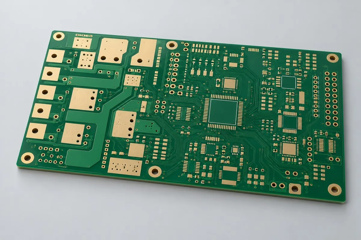
Six-layer FR4 power/digital board fabrication requires review against current drawings. Six-layer FR4 power/digital bare boards are fabricated around PWM, sampling, high-current loops, and terminal dimensions. Power copper of 70µm and signal copper of 35µm are reference allocations; review resin fill around heavy copper together with return paths. Deliver copper-weight/hole-wall copper records and specified TDR; thermal verification requires actual load boundaries.
Six-layer FR4 PCB work first requires a defined bare-board prototype or production scope. Please provide Gerber data, drill files, board outline, and layer stackup, materials/processes, quantities, and manufacturing acceptance requirements. Six-layer FR4 with two copper weights incorporates power capacity and signal returns in one stackup
Review of six-layer FR4 power/digital boards starts with six-layer FR4 power copper of 70µm and signal copper of 35µm. Quotations also require PWM, sampling-loop, and terminal dimensions. Subsequent specification and manufacturing-input tables link key design targets to inspection methods.
Why use this structure for power/digital boards?
When digital management and DC power share a board, six-layer FR4 separates power copper from signal reference planes. Inner power copper of 70µm, signal copper of 35µm, and outer copper of 70µm are this page's reference allocation, suitable for power-control or motor-control logic sections, unlike four-layer acquisition boards carrying only small signals.
What does a six-layer FR4 power/digital board cost, and how is heavy copper priced?
Itemize this quotation by 70µm power copper, 35µm signal copper, and 70µm outer-layer targets; do not price all six layers as one copper weight. Via arrays, resin filling, ENIG, and specified digital 100Ω coupons affect processing. Load/thermal verification is separate. Compare quotations against the same layer-specific copper drawing to prevent unexplained reductions in power copper in lower-priced options.
Quotation terms depend on the approved files, quantity, material supply, tests and delivery requirements.
Prepare a structured RFQ or use the short inquiry form.
Enter the following items in one itemized quotation: specify cost units and tax/shipping basis, with separate columns for first orders and same-revision repeat orders. The table is a procurement breakdown method, not a ready-made price list; reference specifications require approval against current fabrication drawings.
| Quotation items and scope | Inputs to confirm for this configuration | Same-revision reorders and changes |
|---|---|---|
| Materials/fabrication, quoted per batch or accepted board | Isola 370HR FR4; 6 layers; inner power copper 70µm/signal copper 35µm; outer base copper 35µm/finished target 70µm | Recurs on repeat orders; material, layer-order, or copper-weight changes require requotation |
| Holes and forming, per approved hole table | Ø0.35mm through-holes; parallel power layer-transition arrays | Same-revision reorders; review processes before changing power/digital coupling |
| Surface finish/packaging, noting areas and batches | ENIG; large power pads are not equivalent to gold-finger contact surfaces | Incurred by actual batch; confirm packaging, storage conditions, and surface-finish substitutions separately |
| Engineering/tooling preparation, identifying one-time or per-batch charges | Power/digital coupling: identify PWM, ADC sampling, and high-current loops to define power-copper and reference-plane partitioning. | Verify file revisions, ownership, and storage condition before reusing old tooling; do not assume reuse is free |
| Structural/special inspections, identifying coupons, hole groups, or samples | Agree on records for critical copper weights, connection points, and isolation dimensions. Manufacturing records support subsequent soldering first articles; bare-board dimensional acceptance does not establish operating temperature rise under power. | List initial prototype validation and per-batch sampling separately; quote per-board requirements separately rather than assuming everything is completed once |
| Delivery scope, reports, and accepted quantity | Six-layer bare PCBs, layer-specific copper drawings, approved via-array/stackup files, electrical testing, and target-net TDR; current-verification records included by agreement. | Retain revision links and batch records on repeat orders; list component assembly, firmware, and complete-unit testing separately |
How should integrated power/digital boards and four-layer acquisition boards be selected?
This configuration handles heavier DC power and digital management together; four-layer acquisition boards emphasize low-level signals and guard rings. Higher currents require adequate conductor cross sections, while precision inputs require cleanliness and return paths. Layer count alone cannot make the designs interchangeable. If the power stage benefits from separate cooling, compare separate control and power boards.
| Comparison Dimension | Six-layer FR4 PCB fabrication | Four-layer FR4 PCB Prototyping |
|---|---|---|
| Material and Grade | Isola 370HR FR4 | Isola 370HR FR4 |
| Layer Count and Structure | 6 Layer | 4 Layer |
| Hole Structure and Dimensions | Ø0.35mm through-holes; parallel power layer-transition arrays | Ø0.30mm through holes; high-impedance input guard rings remain uninterrupted by through holes |
| Application | Digital DC power management; motor-control logic supplies | Bridge-sensor acquisition; precision ADC front ends |
How should copper weight, via arrays, and differential traces be designed together on a power board?
Separate power paths from digital nets. Check power paths for cross section, length, voltage drop, and temperature rise; calculate digital geometry from reference planes and interface rules. Calculate power-transition hole-wall copper and via counts together with copper paths. Heavy copper cannot retain fine-signal minimum clearances. Finally check lamination copper-density balance and high-di/dt loops.
| Review step | Project inputs | Reviewable output |
|---|---|---|
| 1 Define use and scope | Identify PWM, ADC sampling, and high-current loops to define power-copper and reference-plane partitioning. | Agree on records for critical copper weights, connection points, and isolation dimensions. |
| 2 Confirm structural requirements | Provide actual terminal-hole/pin dimensions and local thermal-design requirements. | Manufacturing records support subsequent soldering first articles; bare-board dimensional acceptance does not establish operating temperature rise under power. |
| 3 Match signal nets to fabrication targets | Digital differential reference target 100Ω; verify power paths for voltage drop/temperature rise | Provide target nets, layer pairs, and verification scope; review alongside Ø0.35mm through holes and parallel via arrays for power layer transitions |
| 4 Confirm quotation and approved revision | Isola 370HR FR4; 1.80mm reference target; ENIG; large power pads are not equivalent to gold-finger contact surfaces | Request quotations using material/pattern/inspection lists at the same revision; list unapproved substitutions as separate alternatives rather than including them in the baseline quotation |
Power Digital Board Manufacturing Specifications
| Specification | Reference configuration or target |
|---|---|
| Material and Grade | Isola 370HR FR4 |
| Layer Count and Structure | 6 Layer |
| Total Board Thickness | 1.80mm reference target |
| Dielectric thickness and interlayer relationship | Digital signal-to-ground target 0.15mm; power-layer spacing target 0.20mm |
| Base Copper and Finished Copper | Inner power copper 70µm/signal copper 35µm; outer base copper 35µm/finished target 70µm |
| Hole Structure and Dimensions | Ø0.35mm through-holes; parallel power layer-transition arrays |
| Trace Width and Spacing | Signal line/space 0.15/0.15mm; power-area reference design 0.25/0.25mm |
| Impedance Target and Measurement Methods | Digital differential reference target 100Ω; verify power paths for voltage drop/temperature rise |
| Surface Finish | ENIG; large power pads are not equivalent to gold-finger contact surfaces |
| Application | Digital DC power management; motor-control logic supplies |
| Deliverables | Six-layer bare PCBs, layer-specific copper drawings, approved via-array/stackup files, electrical testing, and target-net TDR; current-verification records included by agreement. |
Balancing resin fill around heavy copper against a separate power board
Larger power-conductor cross sections require more lamination resin fill and soldering heat. Increasing copper weight across the board does not permit retaining previous fine-line rules. If a high-current power stage benefits from separate cooling, use a separate heavy-copper/metal-core board; this six-layer board prioritizes functional integration.
Parallel via arrays and high-di/dt return paths: manufacturing checks
Review power-transition via-array area and hole-wall copper together with copper paths; high-current nets must not obstruct thermal pads or test points. Balance inner-layer copper density in paired layers, and define switching-supply high-di/dt loops and digital reference grounds according to the circuit.
Hole-wall copper, electrical testing, and specified digital-net TDR: acceptance checks
Inspect finished copper, hole-wall copper, layer registration, and electrical continuity/isolation on bare boards; perform TDR on specified digital nets. Verify power sections for voltage drop/temperature rise under defined load/cooling conditions. Do not infer rated power directly from copper weight.
Power Digital Board Delivery Scope
Applications: DC power digital management; motor-control logic power boards.
Six-layer bare PCBs, layer-specific copper drawings, approved via-array/stackup files, electrical testing, and target-net TDR; current-verification records included by agreement.
PWM, sampling loops, and terminal dimensions: RFQ inputs
Submit PWM, sampling loops, and terminal dimensions to turn the listed design targets into inspectable fabrication drawings. The inputs below define artwork, material, or structural inspection scope; freeze the quotation revision with the approved drawings.
| Required project inputs | Engineering Decisions Affected | Records/delivery as agreed in the order |
|---|---|---|
| Power Digital Coupling | Identify PWM, ADC sampling, and high-current loops to define power-copper and reference-plane partitioning. | Agree on records for critical copper weights, connection points, and isolation dimensions. |
| Terminal thermal mass | Provide actual terminal-hole/pin dimensions and local thermal-design requirements. | Manufacturing records support subsequent soldering first articles; bare-board dimensional acceptance does not establish operating temperature rise under power. |
Six-layer FR4 PCB fabrication: pricing, selection, and purchasing FAQs
What does a six-layer FR4 power/digital board cost, and how is heavy copper priced?
A project-specific quotation requires review of the available files, quantity, materials, requested tests, delivery destination, taxes, shipping, and trade terms. Add specified materials, processes, and inspections not yet included to the total cost. Standard board references do not cover every configuration of this product. Any formula on this page organizes cost inputs; it is not a quoted rate.View cost items, calculation conditions, and sources.
How should integrated power/digital boards and four-layer acquisition boards be selected?
This configuration prioritizes integration of heavier DC power and digital management; four-layer acquisition boards prioritize high-impedance inputs, guard rings, and cleanliness. Power-conductor cross section cannot replace analog return paths. Compare separate boards if the power stage needs independent cooling, including interboard connections and installation in total cost. View Specific Comparison Basis
How should copper weight, via arrays, and differential traces be designed together on a power board?
Check power-path voltage drop/temperature rise using cross section, length, and thermal conditions; calculate digital impedance from layer pairs and interface rules. Review power via arrays with copper paths. Heavy copper cannot retain fine-line limits; finally check lamination balance and high-di/dt returns. View Specific Comparison Basis
Can a six-layer FR4 power board replace an aluminum-core power board?
Compare thermal paths as well as current. FR4 copper allocation provides electrical cross section, while metal-core construction supports mounting and cooling. Actual hotspots and heatsinks may require a separate power structure.
Can a six-layer board's 100Ω report establish power-path current capacity?
No. TDR covers specified digital nets. Power paths require voltage-drop and temperature-rise records under defined conditions; via arrays and connectors also limit current. Include the two verification scopes separately in the order.
Does the power/digital board quotation include digital-control software?
Bare-board fabrication excludes MCU software, components, and motor-control commissioning. For functional boards, provide the BOM and software/test scope, and compare fabrication, assembly, and development costs separately.
Would using the same copper weight on power and signal layers simplify a six-layer power/digital board?
Uniform heavy copper may increase fine-signal etching and resin-fill demands, while uniform thin copper may provide insufficient power cross section. First allocate copper weights and return-path responsibilities around PWM, ADC, and high-current loops. Compare processes against identical voltage-drop/temperature-rise and digital-link targets; do not remove layer definitions merely to simplify purchasing tables.
How do per-board and per-panel six-layer FR4 PCB fabrication quotations compare?
Retain representative inspection locations in both heavy-copper power and signal areas, and include complete terminal holes and parallel via arrays in panels. Do not change PWM/ADC return paths for utilization. State deliverable boards per panel, actual panels purchased, and individual-board/panel delivery format. Calculate fabrication cost per board by dividing actual panel processing cost by the corresponding accepted board count. Itemize preparation, special inspections, and packaging separately; theoretical utilization cannot guarantee yield.
How should initial one-time charges and reorder costs be separated for six-layer FR4 PCB fabrication?
For the first order, confirm power/digital coupling and terminal thermal-mass information, and identify whether engineering, tooling, or test preparation is charged once. Agree on records for critical copper weights, connection points, and isolation dimensions. Verify files and ownership before reusing tooling. Current-batch materials, processing, and approved inspections still apply; itemize preparation required by changes instead of relying on the old order total.
Can I obtain a six-layer FR4 PCB fabrication budget before power/digital coupling information is complete?
Provide the application, board outline, quantity, and available drawings for a budget identifying missing inputs. Formal review requires identification of PWM, ADC sampling, and high-current loops to define power-copper and reference-plane partitioning. The corresponding deliverable is agreed records for critical copper weights, connection points, and isolation dimensions. Confirm fabrication/inspection pricing after these conditions are frozen. Initial inquiries do not require every file, but estimates do not cover undefined structures.
What needs reconfirmation when materials, hole tables, or mounting conditions change on a six-layer FR4 PCB fabrication reorder?
Provide actual terminal-hole/pin dimensions and local thermal-design requirements. Manufacturing records support subsequent soldering first articles; bare-board dimensional acceptance does not establish operating temperature rise under power. Map each change to previous material, hole-table, and mechanical files to determine whether drawings, processes, or measurements must change. Retaining the product name and layer count does not establish identical reorder conditions.
What configurations should be compared when two six-layer FR4 PCB fabrication quotations specify the same material?
Define layer-specific 70µm power and 35µm signal copper, then separately review 100Ω digital coupons and power voltage-drop/temperature-rise results. The reports cannot substitute for each other, and large power pads are not gold-finger contact surfaces.
Which six-layer FR4 PCB fabrication reports should link to board IDs before moving from prototypes to production?
Agree on records for critical copper weights, connection points, and isolation dimensions. Manufacturing records support subsequent soldering first articles; bare-board dimensional acceptance does not establish operating temperature rise under power. Link material lots, approved fabrication files, and these inspection results to the current prototype ID, and use the revision with issues closed for production. Old coupon or artwork reports support comparison but cannot replace current manufacturing inputs; define uncovered system-level items separately.
How can I tell whether a lower small-batch six-layer FR4 PCB fabrication unit price reduces total purchasing cost?
A stackup combining thin signal copper with heavy power copper includes etching/resin fill, digital coupons, and power verification costs. A simpler uniform-copper quotation does not establish lower total cost for identical electrical/thermal targets. Add preparation, fabrication, agreed inspections, packaging, and shipping, then divide by the accepted delivery quantity. Compare total cost and per-board allocation for identical scope. Use current RFQ amounts and rates rather than assuming a fixed reduction.
Power digital board compared with adjacent board types
Configuration distinction: six-layer FR4 with two copper weights incorporates power capacity and signal returns in one stackup
- Double-sided FR4 relay control board — Double-sided 2oz reference finished copper serves load circuits; low signal density makes insulation layout important
- Four-layer FR4 precision analog acquisition board — Continuous reference ground and guard-ring regions support weak signals, avoiding shared circuits with relay loads
FR4 PCB complete product catalog · All PCB Products
Power digital board materials and design basis
- Engineering reference | Isola 370HR material: high Tg and frequency-dependent parameters: Published manufacturer material data
- Engineering reference | PCB thermal estimates: power dissipation, copper area, and junction-temperature checks: Thermal design methods
- Engineering reference | General high-speed interface layout: return paths, length, and layer transitions: Design methodology
When citing the information above, record material revisions and design conditions for six-layer FR4 power copper of 70µm and signal copper of 35µm. First-article checks focus on hole-wall copper, electrical testing, and specified digital-net TDR. Update fabrication drawings and inspections before release if materials, copper weight, or via structures change.
Request Quote for This PCB Configuration: Reference product ID 341, attach key circuits/interfaces and quantities, and identify specifications to retain or adjust.